- Home
- About Journals
-
Information for Authors/ReviewersEditorial Policies
Publication Fee
Publication Cycle - Process Flowchart
Online Manuscript Submission and Tracking System
Publishing Ethics and Rectitude
Authorship
Author Benefits
Reviewer Guidelines
Guest Editor Guidelines
Peer Review Workflow
Quick Track Option
Copyediting Services
Bentham Open Membership
Bentham Open Advisory Board
Archiving Policies
Fabricating and Stating False Information
Post Publication Discussions and Corrections
Editorial Management
Advertise With Us
Funding Agencies
Rate List
Kudos
General FAQs
Special Fee Waivers and Discounts
- Contact
- Help
- About Us
- Search


The Open Fuels & Energy Science Journal
(Discontinued)
ISSN: 1876-973X ― Volume 11, 2018
Numerical Calculation of Flow Characteristics of Enhanced Foam System in Porous Medium
Chengli Zhang1, *, Guodong Qu1, Guoqiang Cui2, Mingxing Bai1
Abstract
Enhanced foam flooding is a chemical flooding technology, which is applied to improve the recovery efficiency of oil and gas. The oil displacement agent of enhanced foam flooding is a foam that the polymer and surfactant solution as liquid. In this paper, three-dimensional mathematical model of unsteady flow is established about enhanced foam system in the porous media, and the numerical calculation method is given to study the enhanced foam flooding. The results show that: the unsteady flow of enhanced foam system in porous media exists flow front, the flow foam average density of flow front reach the peak; enhanced foam flooding can form the oil bank in the displacement front and the oil saturation of the oil bank reaches about 0.55, the oil bank can produce effective drive to remain oil and then improve oil recovery.
Article Information

Identifiers and Pagination:
Year: 2016Volume: 9
First Page: 29
Last Page: 36
Publisher Id: TOEFJ-9-29
DOI: 10.2174/1876973X01609010029
Article History:
Received Date: 17/10/2014Revision Received Date: 05/08/2016
Acceptance Date: 10/08/2016
Electronic publication date: 21/09/2016
Collection year: 2016
open-access license: This is an open access article licensed under the terms of the Creative Commons Attribution-Non-Commercial 4.0 International Public License (CC BY-NC 4.0) (https://creativecommons.org/licenses/by-nc/4.0/legalcode), which permits unrestricted, non-commercial use, distribution and reproduction in any medium, provided the work is properly cited.
* Address correspondence to this author at the School of Petroleum Engineering, Northeast Petroleum University, Daqing, 163318, China; Tel: +8613845948796; Fax: +8604596503482; E-mail: zhangchengli0303@163.com
| Open Peer Review Details | |||
|---|---|---|---|
| Manuscript submitted on 17-10-2014 |
Original Manuscript | Numerical Calculation of Flow Characteristics of Enhanced Foam System in Porous Medium | |
1. INTRODUCTION
In China, the main development way is water flooding in middle-high permeability reservoir. Parts of the oilfield have entered into the ultra-high water cut stage, water flooding recovery can only reach 40%. Due to the long-term washing of the injected water, the heterogeneity of the reservoir and the invalid loop of the injected water is more serious. So it must use tertiary oil recovery method to improve oil recovery. Foam flooding has gradually become one of the main enhance oil recovery technologies in Eastern China oil field after polymer flooding technology [1Bojun, W.; Yongbin, W.; Youwei, J.; Jinzhong, L.; Xialin, Z.; Songlin, L. Physical simulation experiments on PVT properties of foamy oil. Acta Petrol. Sin., 2012, 33(1), 96-100.-3Xinqiang, Y.; Keliang, W.; Jinfeng, C.; Xiaobo, L. Research on oil-displacement effect of composite hot foam system. Acta Petrol. Sin., 2010, 31(1), 87-90.]. Enhanced foam flooding is a new kind of chemical flooding technology [4Zenglin, W. Enhanced Foam Flooding for Improving Oil Recovery; Press of Science and Technology of China: Beijing, 2007, pp. 26-37.-6Li, B.F.; Li, Z.M.; Liu, Z.P.; Zhao, L.; Li, S.Y.; Lin, R.Y.; Wang, G.H. Experiment on profile control and flooding by multiphase foam system. J. China Univ. Pet., 2010, 34(4), 93-98.], enhanced foam system is a complex fluid and it’s rheology and stability is affected by many factors, and it has ultra-low interfacial tension, higher viscosity and gas obstruction action [7Zhao, C.J.; Ma, C.J.; Yang, Z.Y.; Yao, S.C. Pilots of ultra-low interfacial tension foam flooding. Pet. Explor. Dev., 2005, 32(1), 127-130.]. Indoor core displacement experiment shows that enhanced foam flooding can improve oil recovery more than 25% than that of water flooding [8Hongmin, Y.; Shaoran, R. Jingluan. Z. A mathematical model and numerical simulation method for air-foam flooding. Acta Petrol. Sin., 2012, 33(4), 653-657.]. Especially the polymer in the enhanced foam system can increase the liquid membrane viscosity of foam and improve foam stability when in contact with the oil, so as to improve the displacement efficiency of enhanced foam system.
2. MATHEMATICAL MODEL
2.1. The Basic Hypothesis
1) The fluid system includes the liquid phase and gas phase (foams), and the non-Newtonian fluid is characterized by a pressure gradient function. 2) Liquid phase of enhanced foam system, as incompressible power-law fluid, is polymer and surfactant solution. The surfactant concentration is constant and the gas phase is regarded as an ideal gas. 3) Surfactant is only found in water phase. Due to its small concentration, the effects on the density and viscosity of each phase can be ignored. 4) Using a modified gas phase relative permeability model to characterize the relative permeability of the foam.
2.2. Gas-liquid Two Phase Mass Conservation Equation
1) Gas-liquid two phase mass conservation equation
Gas-liquid two phase mass conservation equation of the three dimensional unsteady flow is an equation about the enhanced foam system in the porous media.
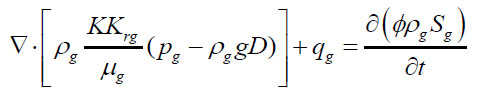
The gas phase:
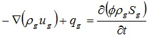 |
(1) |
The liquid phase:
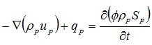 |
(2) |
Where ϕ is the core porosity, dimensionless; ρg is the gas phase density, kg/m3; µg is the Darcy rate of gas phase, m/s; qg is the gas injection rate, kg/m3s; Sg is the gas phase saturation, dimensionless; ρp is the liquid density, kg/m3; µp is the Darcy rate of liquid phase, m/s; qp is liquid injection rate, kg/m3.s; Sp is liquid saturation, dimensionless.
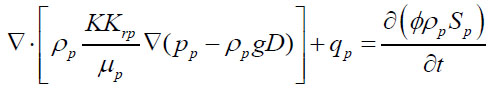
2) Gas-liquid two phase motion equations
The gas phase:
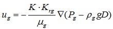 |
(3) |
The liquid phase:
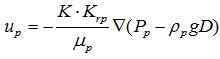 |
(4) |
Where K is the core permeability, m2; Krg is the gas phase relative permeability, dimensionless; Pg is the liquid pressure, Pa; μg is the gas phase viscosity, Pa.s; Krp is the liquid phase relative permeability, dimensionless; Pp is the liquid pressure, Pa; μp is the liquid apparent viscosity, Pa.s, D is the vertical depth of oil reservoir.
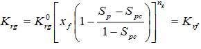
(1) The gas phase relative permeability:
 |
(5) |
Where
 is the calculation gas phase relative permeability coefficient, dimensionless; ng is the calculation gas phase relative permeability power exponent, dimensionless, K rf is the foam effective permeability, dimensionless.
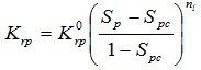
(2) The liquid phase relative permeability:
 |
(6) |
Where
 is the calculation liquid phase relative permeability coefficient, dimensionless; Spc is the bound liquid phase saturation, dimensionless; nl is the calculation liquid phase relative permeability power exponent, dimensionless.
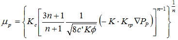
(3) Liquid apparent viscosity
Apparent viscosity expression of power law fluid:
 |
(7) |
Where n is the power law fluid liquidity index, dimensionless; Kc is the power law fluid consistency coefficient, Pa.s"; c' is the pore tortuosity coefficient, dimensionless.
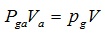
3) State equation
The gas phase state equation is:
 |
(8) |
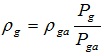 |
(9) |
Where Pga is the pressure under the condition of the standard atmospheric pressure, Pa; Va is the gas volume under the condition of the standard atmospheric pressure, m3; Pg is the gas phase pressure, Pa; V is the gas volume under the gas phase pressure, m3; ρga is the gas density under the condition of the standard atmospheric pressure, kg / m3.
4) The basic differential equation
Take the motion equations (3) and (4) into the mass conservation equations (1) and (2), and then the basic differential equation of gas-liquid two phase of the three-dimensional unsteady flow about the enhanced foam system in the porous media is given.
The gas phase:
 |
(10) |
The liquid phase:
 |
(11) |
2.3. The Foam Amount Balance Equation
Only using the gas liquid two phase basic differential equation to describe the flow law of enhancing foam system in porous media is not enough, the structure change of foam when it flows in porous media must be considered, such as the production, burst, coalescence, migration and retention, start of foam and so on. The foam amount balance equation describes the number and size of foam change and its effect on gas phase relative permeability and the effective viscosity through the average density of flowing foam and the average density of interception foam.
Based on the previous; research results, the enhanced foam system amount balance equation under the condition of the average foam size is [9Kovscek, A.R.; Radke, C.J. Fundamentals of Foam Transport in Porous Media. Foams: Fundamentals and Applications in the Petroleum Industry; American Chemical Society: Washington, DC, 1994, pp. 115-163.
[http://dx.doi.org/10.1021/ba-1994-0242.ch003] -16Teng, L.; Zhaomin, L.; Jing, L.; Ran, L. A mathematical model of foam flooding based on foam microscopic seepage characteristics. Chinese. J. Comput. Phys., 2012, 29(04), 519-524.]:
 |
(12) |
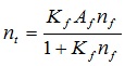
Where nf, nt is the average density of the flowing foam and the trapping foam; Xf, Xt is the shunt volume of the flowing foam and the trapping foam, uf is the Darcy flow rate of gas; k1 is the foam formation rate constant; k-1 is the coalescence rate constant; vw, vf is the real flow rate of liquid and gas;
 is the gas injection(output) rate;
 is the flowing foam rate in well point.
Coalescence rate constant is:
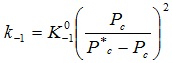 |
(13) |
Pc is the capillary force. Expression of critical capillary force is:
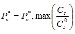 |
(14) |
Where Cs, Cs0 is the surfactant concentration and concentration reference value of liquid phase; Pc*, max is maximum critical capillary force.
Calculation formula of foam viscosity as follows [17Khatlb, Z.I.; Hirasaki, G.J.; Falls, A.H. Effects of capillary pressure on coalescence and phase mobilities in foams flowing through porous media. Soc. Petrol. Eng., 1988, 919-926.]:
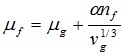 |
(15) |
Where α is the viscosity coefficient which is related to the structure and concentration of surfactant.
The fraction of trapping foam in the foam can be written as:
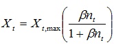 |
(16) |
Where Xt,max is the maximum trapping foam fraction, β is the empirical constant.
2.4. Auxiliary Equation
1) The equilibrium relation between the flowing foam and the tarpping foam:
 |
(17) |
2) The saturation relationship:
 |
(18) |
3) Capillary pressure equation:
 |
(19) |
2.5. Model Validation
Using IMPES(implicit pressure explicit saturation) method to calculate the mathematical model of three dimensional unsteady flow of enhanced foam system in porous medium. This method is implicit pressure explicit saturation method. That is, it can use implicit expression to solve pressure equation, and show the equation of solving saturation.
In order to verify the correctness of the model, firstly, the experiment of enhanced foam flooding after water flooding was carried out. The experimental system and flow chart of N2 foam flooding is shown in Figs. (1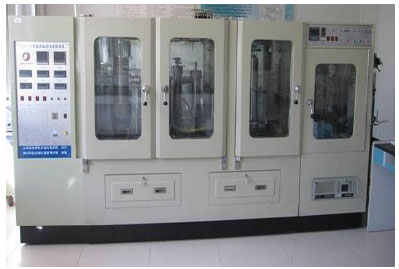 and 2
and 2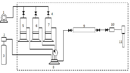 ).
).
 |
Fig. (1) The experimental system of foam flooding. |
1 Injection pump 2 Flowmeter 3 N2 4 Valve 5 Foamer 6 Oil 7 Formation water 8 Pressure gauge
9 Core 10 Back pressure valve 11 Separator
 |
Fig. (2) The flow chart of N2 foam displacement experiment. |
Experimental methods: the process of core flooding was connected, installed and debugged, and the artificial quartz sand model (size 25mm×300mm, permeability about 1.5μm2, pore volume about 55cm3) was inserted into the process, then the water was injected at speed of 0.5 ml/min until the flooding pressure steadied, then the concentration 0.5% foam agent solution mixed with nitrogen was injected into the core by six-way valve, and the pressure difference at both ends of the core was recorded until it stable, and the experimental data are shown in Fig. (3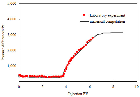 ).
).
The experimental results of enhanced foam flooding after water flooding were calculated and fitted. The foam is injected with the polymer solution which concentration is 1250mg/L. As a result of the existence of polymer, the stability of the enhanced foam system is enhanced which can make the foam exist steadily in oil model. In enhanced foam flooding experiment, the enhanced foam system is injected after water flooding, the differential pressure rising rapidly. Fitting results are shown in Fig. (3). It can be seen from the fitted curve that mathematical model calculation value and experimental value are consistent.
 |
Fig. (3) Fitting curve of enhanced foam flooding about oil pressure differential. |
3. NUMERICAL SIMULATION RESEARCHES ON ENHANCED FOAM FLOODING
Numerical calculation to unsteady flow of enhanced foam system in porous medium is taken and the distribution of oil phase saturation and flowing foam average density.
3.1. Average Density Distribution of Flowing Foam of the Enhanced Foam System
The distribution of average density
of the flowing foam, which is unsteady flow of enhanced foam system in porous media, is shown in Fig. (4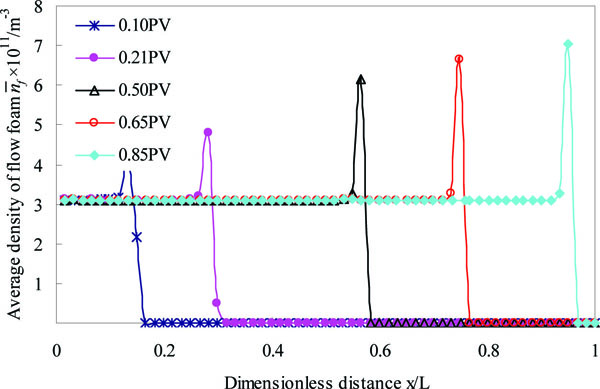 ). It can be seen from Fig. (4) that the unsteady flow of the enhanced foam system in porous media exists flow front. The average density of flowing foam of the flow front reaches the peak. When the liquid saturation of flow front steep rises to 1.0, the capillary force falls, the structure of foam becomes thinner and it leads to the average density of flowing foam appeared peak. In addition, the average density peak of the flowing foam of the flow front increases with the injection time. This is because the foam piston strength increases with the injection time.
 |
Fig. (4) The distribution of the average density of the flowing foam. |
3.2. Oil Phase Saturation Distribution of Enhanced Foam Flooding
Fig. (5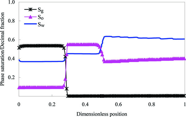 ) is the core phase saturation distribution after enhanced foam flooding 0.2 PV. It can be seen that due to the high viscosity characteristics of the foam, the steady foam system is formed at the injection side, the oil saturation drop to around 0.1 in the part where is displaced. In the displacement front, the oil bank is formed. The oil saturation of oil bank reaches about 0.55. The oil saturation which is residual oil saturation after water flooding in outlet is about 0.38.
 |
Fig. (5) Oil phase saturation distribution of enhanced foam flooding. |
CONCLUSION
(1) Based on the principle of conservation of mass, considering the characteristics of foam in porous media, such as the production, burst, coalescence, migration and retention, start and so on, the mathematical model of the three-dimensional unsteady flow of enhanced foam system in porous media is established, and a numerical calculation is taken to the model.
(2) Average density distribution of the flowing foam of the enhanced foam system is analyzed through numerical simulation. The results show that the unsteady flow of the enhanced foam system in porous media exists flow front. The average density of flowing foam of the flow front reaches the peak.
(3) In the process of enhanced foam flooding, oil bank is formed in displacement front. Oil saturation of oil bank reaches about 0.55 and can produce effective drive to residual oil.
CONFLICT OF INTEREST
The authors confirm that this article content has no conflicts of interest.
ACKNOWLEDGEMENTS
This work was financially supported by the Natural Science Foundation of Heilongjiang Province (No. E2016014).
REFERENCES
| [1] | Bojun, W.; Yongbin, W.; Youwei, J.; Jinzhong, L.; Xialin, Z.; Songlin, L. Physical simulation experiments on PVT properties of foamy oil. Acta Petrol. Sin., 2012, 33(1), 96-100. |
| [2] | Sifu, Z. ASP-Foam pilot test of Daqing oil field. Acta Petrol. Sin., 2001, 22(1), 49-53. |
| [3] | Xinqiang, Y.; Keliang, W.; Jinfeng, C.; Xiaobo, L. Research on oil-displacement effect of composite hot foam system. Acta Petrol. Sin., 2010, 31(1), 87-90. |
| [4] | Zenglin, W. Enhanced Foam Flooding for Improving Oil Recovery; Press of Science and Technology of China: Beijing, 2007, pp. 26-37. |
| [5] | Guohua, Z.; Xinwang, S.; Qiwei, W.; Ping, G.; Xiang-liang, L.; Xue-song, L. Application of foam combination flooding in Shengli oilfield. Pet. Explor. Dev., 2006, 33(3), 369-373. |
| [6] | Li, B.F.; Li, Z.M.; Liu, Z.P.; Zhao, L.; Li, S.Y.; Lin, R.Y.; Wang, G.H. Experiment on profile control and flooding by multiphase foam system. J. China Univ. Pet., 2010, 34(4), 93-98. |
| [7] | Zhao, C.J.; Ma, C.J.; Yang, Z.Y.; Yao, S.C. Pilots of ultra-low interfacial tension foam flooding. Pet. Explor. Dev., 2005, 32(1), 127-130. |
| [8] | Hongmin, Y.; Shaoran, R. Jingluan. Z. A mathematical model and numerical simulation method for air-foam flooding. Acta Petrol. Sin., 2012, 33(4), 653-657. |
| [9] | Kovscek, A.R.; Radke, C.J. Fundamentals of Foam Transport in Porous Media. Foams: Fundamentals and Applications in the Petroleum Industry; American Chemical Society: Washington, DC, 1994, pp. 115-163. [http://dx.doi.org/10.1021/ba-1994-0242.ch003] |
| [10] | Guo, C.; Guangzhi, L.; Jingang, N. Equinalent numerical simulation model for foam flowing in porous medium. Petrol. Geol. Oilfield Devel. Daqing, 2001, 2, 72-75. |
| [11] | Hao, C.; Zhaoxi, L. Capillary crossflow in foam flood and its numerical simulation. J. Chongqing Univ., 2003, 23, 161-165. |
| [12] | Kovscek, A.R.; Patzek, T.W.; Radke, C.J. Simulation of foam transport in porous media. Soc. Petrol. Eng., 1993, 309-318. |
| [13] | Roseen, W.R.; Zeilinger, S.C.; Shi, J.; Lim, M.T. Mechanistic simulation of foam processes in porous media. Soc. Petrol. Eng., 1994, 493-500. |
| [14] | Palls, A.H.; Hirasaki, G.J.; Patzek, T.W.; Gaualltz, D.A.; Miller, D.D.; Ratulowsk, T. Development of a mechanistic foam simulator: the population balance and generation by snap-off. Soc. Petrol. Eng., 1988, 884-892. |
| [15] | Patzek, T.W. Description of foam flow in porous media by the population balance method. Soc. Petrol. Eng., 1986, 1-9. |
| [16] | Teng, L.; Zhaomin, L.; Jing, L.; Ran, L. A mathematical model of foam flooding based on foam microscopic seepage characteristics. Chinese. J. Comput. Phys., 2012, 29(04), 519-524. |
| [17] | Khatlb, Z.I.; Hirasaki, G.J.; Falls, A.H. Effects of capillary pressure on coalescence and phase mobilities in foams flowing through porous media. Soc. Petrol. Eng., 1988, 919-926. |