- Home
- About Journals
-
Information for Authors/ReviewersEditorial Policies
Publication Fee
Publication Cycle - Process Flowchart
Online Manuscript Submission and Tracking System
Publishing Ethics and Rectitude
Authorship
Author Benefits
Reviewer Guidelines
Guest Editor Guidelines
Peer Review Workflow
Quick Track Option
Copyediting Services
Bentham Open Membership
Bentham Open Advisory Board
Archiving Policies
Fabricating and Stating False Information
Post Publication Discussions and Corrections
Editorial Management
Advertise With Us
Funding Agencies
Rate List
Kudos
General FAQs
Special Fee Waivers and Discounts
- Contact
- Help
- About Us
- Search


The Open Fuels & Energy Science Journal
(Discontinued)
ISSN: 1876-973X ― Volume 11, 2018
Flow Characteristics of a Low Reynolds Number Jet in Crossflow with an Obstacle Block
Jianlong Chang1, 3, *, Xudong Shao2, Xiao Hu3, Shuangbiao Zhang3
Abstract
The jet in crossflow at very low Reynolds number (Re=100) with and without block is performed by means of large eddy simulation for the jet-to-crossflow velocity ratios (r) ranging from 1 to 3, and the corresponding flow characteristics are compared. The results show that the time-averaged particle trajectories of the jet are slightly changed if a block is presented, and the mixed vortices are weakened. The existence of the block also can accelerate the formation of stable counter-rotating vortex pair. At lower velocity ratio (r=1), the block has little effect on the jet in crossflow with a symmetrically positive and negative kidney shaped vortices. As the velocity ratio increases, the effect of block not only can generate an asymmetry of positive and negative kidney shaped vortices, but also it can reinforce the interaction between the positive and negative vortices in the jet in crossflow. The effect of block on the temperature field is also analyzed in detail.
Article Information

Identifiers and Pagination:
Year: 2016Volume: 9
First Page: 37
Last Page: 46
Publisher Id: TOEFJ-9-37
DOI: 10.2174/1876973X01609010037
Article History:
Received Date: 11/3/2016Revision Received Date: 08/08/2016
Acceptance Date: 16/08/2016
Electronic publication date: 21/09/2016
Collection year: 2016
open-access license: This is an open access article licensed under the terms of the Creative Commons Attribution-Non-Commercial 4.0 International Public License (CC BY-NC 4.0) (https://creativecommons.org/licenses/by-nc/4.0/legalcode), which permits unrestricted, non-commercial use, distribution and reproduction in any medium, provided the work is properly cited.
* Address correspondence to this author at the College of Mechatronic Engineering, North University of China, Taiyuan, Shanxi, 10081, China; Tel: +86-13811 113133; E-mail: changjianlong1989@126.com
| Open Peer Review Details | |||
|---|---|---|---|
| Manuscript submitted on 11-3-2016 |
Original Manuscript | Flow Characteristics of a Low Reynolds Number Jet in Crossflow with an Obstacle Block | |
INTRODUCTION
As a fundamental flow phenomenon, the jet in crossflow (JICF) has many combustion engineering and environmental applications in efficient dispersion of the species [1Muppidi, S.; Mahesh, K. Direct numerical simulation of round turbulent jets in crossflow. J. Fluid Mech., 2007, 574, 59-84.
[http://dx.doi.org/10.1017/S0022112006004034] , 2Campolo, M.; Salvetti, M.V.; Soldati, A. Mechanisms for microparticle dispersion in a jet in crossflow. AlChE J., 2005, 51(1), 28-43.
[http://dx.doi.org/10.1002/aic.10301] ]. Because of its important engineering application and theoretical value, JICF has drawn attention of many researchers [3Kawai, S.; Lele, S.K. Large-eddy simulation of jet mixing in supersonic crossflows. AIAA J., 2010, 48(9), 2063-2083.
[http://dx.doi.org/10.2514/1.J050282] -21Gutmark, E.J.; Grinstein, F.F. Flow control with noncircular jets. . Annu. Rev. Fluid Mech., 1999, 31(1), 239-272.
[http://dx.doi.org/10.1146/annurev.fluid.31.1.239] ] in the past decades.
The evolution for the mixed vortices of the JICF was investigated by Kawai [3Kawai, S.; Lele, S.K. Large-eddy simulation of jet mixing in supersonic crossflows. AIAA J., 2010, 48(9), 2063-2083.
[http://dx.doi.org/10.2514/1.J050282] ] and Rana [4Rana, Z.A.; Thornber, B.; Drikakis, D. Transverse jet injection into a supersonic turbulent cross-flow. Phys. Fluids, 2011, 23(4), 046103.
[http://dx.doi.org/10.1063/1.3570692] ] by using the large eddy simulation methods. In the research of Majander [5Majander, P.; Siikonen, T. Large-eddy simulation of a round jet in a cross-flow. Int. J. Heat Fluid Flow, 2006, 27(3), 402-415.
[http://dx.doi.org/10.1016/j.ijheatfluidflow.2006.01.004] ], large eddy simulation of a round JICF was described in the steady and unsteady boundary conditions. The numerical simulation results were coincident with the experimental data. The existence of shear layer vortices with a ring-like shape and counter-rotating vortex pairs was proved, and the analysis of flow characteristics were performed simply. The flow around a perforated plate using a single-hole, bi-periodic domain had been reported by Mendez [6Mendez, S.; Nicoud, F. Large-eddy simulation of a bi-periodic turbulent flow with effusion. J. Fluid Mech., 2008, 598, 27-65.
[http://dx.doi.org/10.1017/S0022112007009664] ] to represent the interaction between several jets and the crossflow. The difference of vortex structures for the flow field and crossflow was analyzed, and the simulations had good consistency with the experimental results.
In the further research, researchers paid more attention to the complex flow field structures in the JICF [7Ben-Yakar, A.; Mungal, M.G.; Hanson, R.K. Time evolution and mixing characteristics of hydrogen and ethylene transverse jets in supersonic crossflows. Phys. Fluids, 2006, 18(2), 026101.
[http://dx.doi.org/10.1063/1.2139684] -12Yuan, L.L.; Street, R.L.; Ferziger, J.H. Large-eddy simulations of a round jet in crossflow. J. Fluid Mech., 1999, 379, 71-104.
[http://dx.doi.org/10.1017/S0022112098003346] ]. Ben-Yakar [7Ben-Yakar, A.; Mungal, M.G.; Hanson, R.K. Time evolution and mixing characteristics of hydrogen and ethylene transverse jets in supersonic crossflows. Phys. Fluids, 2006, 18(2), 026101.
[http://dx.doi.org/10.1063/1.2139684] ] analyzed the evolution of the ring-like vortices, and the forming frequency was obtained. The supersonic jet interaction flow field with a sonic circular jet using Reynolds-averaged Navier–Stokes (RANS) was performed by Viti [8Viti, V.; Neel, R.; Schetz, J.A. Detailed flow physics of the supersonic jet interaction flow field. Phys. Fluids, 2009, 21(4), 046101.
[http://dx.doi.org/10.1063/1.3112736] ]. The vortex structures in the three-dimensional average flow field were analyzed. The formations of three special shocks including a barrel shock, a bow shock, and a separation-induced shock wave were observed. Camussi [9Camussi, R.; Guj, G.; Stella, A. Experimental study of a jet in a crossflow at very low Reynolds number. J. Fluid Mech., 2002, 454, 113-144.
[http://dx.doi.org/10.1017/S0022112001007005] ] performed the flow visualizations and phase-averaged particle image velocimetry (PIV) measurements of a jet in crossflow configuration at very low Reynolds numbers (Re=100), which were achieved in a water tunnel with the velocity ratios ranging from 1.5 to 4.5. The corresponding results showed that the principal vortex systems from the interaction of the jet with the crossflow at low Reynolds number were the same as those observed at larger Reynolds numbers. Salewski [10Salewski, M.; Stankovic, D.; Fuchs, L. Mixing in circular and non-circular jets in crossflow. . Flow Turbul. Combus., 2008, 80(2), 255-283.
[http://dx.doi.org/10.1007/s10494-007-9119-x] ] studied the vortex structures in the field of a jet in crossflow by using computational (large eddy simulation) and experimental (particle image velocimetry and laser-induced fluorescence) techniques. The corresponding scalar fields and turbulence characteristics were compared for circular, elliptic, and square nozzles. The results had shown that JICF with high aspect ratio and blunt square jet nozzle demonstrated excellent mixing performance. Cárdenas [11Cárdenas, C.; Denev, J.A.; Suntz, R.; Bockhorn, H. Study of parameters and entrainment of a jet in cross-flow arrangement with transition at two low Reynolds numbers. Exp. Fluids, 2012, 53(4), 965-987.
[http://dx.doi.org/10.1007/s00348-012-1333-1] ] had conducted the investigation in the Reynolds-number range, the trajectories were very similar for both cases (with a slightly lower trajectory in the high-Re case), indicating that the Reynolds number didn't have a significant influence on the jet-trajectory and hence on the jet-penetrtion. Large eddy simulations were performed by Yuan [12Yuan, L.L.; Street, R.L.; Ferziger, J.H. Large-eddy simulations of a round jet in crossflow. J. Fluid Mech., 1999, 379, 71-104.
[http://dx.doi.org/10.1017/S0022112098003346] ] at two jet-to-crossflow velocity ratios, 2.0 and 3.3, and two Reynolds numbers, 1050 and 2100. The counter-rotating vortex pair was demonstrated to derive from a pair of hanging vortices. The numerical simulation had high consistency with the experimental results, which proved that large eddy simulation method for JICF at low Reynolds number was also feasible.
The most important physical phenomena in the JICF is the vortex structure as shown in Fig. (1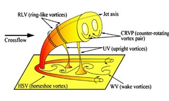 ), including the counter-rotating vortex pair (CRVP), upright vortices (UV), ring-like vortices (RLV), horseshoe vortex (HSV) and wake vortices (WV).
 |
Fig. (1) Vortex structure of a JICF [13Cárdenas, C.; Suntz, R.; Denev, J.A.; Bockhorn, H. Two-dimensional estimation of Reynolds-fluxes and-stresses in a Jet-in-Crossflow arrangement by simultaneous 2D-LIF and PIV. Appl. Phys. B, 2007, 88(4), 581-591. [http://dx.doi.org/10.1007/s00340-007-2734-3] ]. |
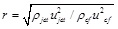
The Reynolds number (Re) and the effective jet-to-crossflow velocity ratio (r) [14Muppidi, S.; Mahesh, K. Study of trajectories of jets in crossflow using direct numerical simulations. J. Fluid Mech., 2005, 530, 81-100.
[http://dx.doi.org/10.1017/S0022112005003514] ] have great effect on the flow field of a JICF:
 |
(1) |
where ujet is the jet velocity, ucf is the velocity of crossflow, ρjet is the density of jet fluid, ρcf is the crossflow fluid density, respectively.
Most of the previous researches on the JICF are conducted at high Reynolds number, while vortex structures of the JICF at low Reynolds number are clearer and more stable. However, the rear of entrance for the ejected jet is usually not an open area in practical engineering applications, but a complex part that may have a variety of different obstacles, such as block, cylinder, and so on. Therefore, it is necessary to investigate the conditions for the existence of obstacles in the JICF.
In this paper, large eddy simulation and analysis for a jet in crossflow at very low Reynolds number (Re=100) with and without block will be performed. While the jet-to-crossflow velocity ratios (r) range from 1 to 3.
FLOW CONFIGURATION AND NUMERICAL METHODS
Flow Configuration and Grid Distribution
As shown in Fig. (2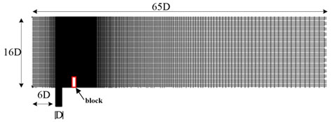 ), the diameter of the round pipe is D. The length, breadth and height of the domain are 65D, 20D and 16D, respectively. The angle between the jet velocity and the crossflow velocity is 90°, the block is located 3D away from the center of the jet nozzle, and the height of the block is 2D. The distance from the entrance of crossflow to the center of the jet nozzle is 6.5D. The length of the ejection pipe is 5D. The structured mesh is adopted in the simulation, the corresponding mesh is refined near the block and the entrance of the jet. The grid independence is also conducted.
 |
Fig. (2) View of the grid. |
In relation to Fig. (2), the boundary conditions conducted in the studied cases are: (1) For the wall at bottom, no-slip boundary condition is conducted excluding the jet exit region. (2) At the crossflow inlet and the jet inlet, the uniform velocity/boundary layer profiles are used. And vcrossflow=1, vjet is varying according to the velocity ratio. (3) At the domain exit, the pressure-outlet outflow boundary condition is adopted.
Numerical Methods
Different from Reynolds Averaged Navier-Stokes Equation (RANS) and Direct Numerical Simulation (DNS), the aim of the large eddy simulation (LES) is to resolve the larger scale of turbulence, and the smaller turbulence is modeled based on the universality. The key idea of LES is to limit the computational cost by only solving the larger scales of the flow while modeling the smaller ones. By filtering process in the large eddy simulation, the vortices less than a certain scale are filtered from the flow field, and then large eddy is calculated. Then the solution of small eddy by solving additional equation is captured at the same time. Consequently, LES is more suitable for engineering applications.
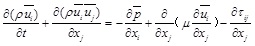
For the LES, the flow is divided into the large-scale eddy and the small-scale eddy. The basic equations of LES can be obtained respectively by filtering Navier-Stokes equation and the continuity equation [15Computional Bridge Aerodynamics Large Eddy Simulation; China Communications Press: Beijing, 2010. ]:
 |
(2) |
 |
(3) |
where ρ is the density of fluid, ui and uj are the velocity components, p is the pressure, μ is the kinematic viscosity coefficient, the variables of formula with an overline are the field variables filtered. Component of subgrid stress tensor is
 , showing the motion effect of small eddy to large eddy. The relationship between
 and
and
 which is on behalf of the components of the strain rate tensor can be expressed as:
 |
(4) |
where νT is the turbulent viscosity, δij is the Kroneker symbol,
is the strain rate tensor after filtering,
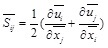 |
(5) |
The tsurbulent viscosity μT can be configured as product between the length scale l and the velocity scale q. Assuming that the magnitude of small-scale is in equilibrium, the length scale and the velocity scale can be defined as
 ,
,
 . Then the turbulent viscosity μT can be expressed as:
 |
(6) |
where the symbol CS repsesents the constant of Smagorinsky, the approximation of the constant is
 |
(7) |
The value measured in the atmosphere for Kolmogorov constant is 1.4, thereby CS ≈ 0.18. However, the value of CS is usually taken as 0.1 in practical application. The symbol
 is the scale of grid filter, and it can be obtained by
 . For unstructured grids,
could be acquired by extracting a cube root for the unit volume.
. For unstructured grids,
could be acquired by extracting a cube root for the unit volume.
 can be captured by
 |
(8) |
RESULTS AND DISCUSSION
Time-averaged Particle Trajectory
The time-averaged particle trajectory is defined as the JICF axis. Fig. (3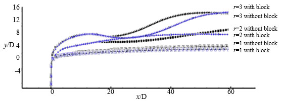 ) shows the time-averaged particle trajectories for the JICF with and without block, respectively. As the jet is ejected from the nozzle, the jet has larger kinetic energy and a stronger penetration compared with the crossflow near the nozzle. Therefore the jet can quickly flow across the boundary layer. It experiences violently exchange of energy and momentum once the jet reaches the crossflow in the flow channel. So the jet begins to deflect at the beginning stage, and complex vortex structures including the CRVP, RLV, UV, WV and HSV are generated.
 |
Fig. (3) Time-averaged particle trajectories for the JICF (Black: cases without block; blue: cases with block). |
It is found that according to the time-averaged particle trajectories for the JICF without block in Fig. (3), the jet penetrates higher, as the jet-crossflow velocity ratio increases. The compared results of the time-averaged particle trajectories for the JICF with and without block demonstrate that the block has little effect on the time-averaged particle trajectories at low velocity ration r=1, only the jet penetration is slightly reduced. A preliminary difference between the trajectories appears at r=2. The time-averaged particle trajectories for the block JICF are similar to the situation at r=1, but the corresponding depth of the jet is enhanced. The trend of the jet penetration without block is firstly reinforced, then reduced, and finally reinforced. The corresponding change of the penetration is not evident. With further argument of the velocity ratio, the time-averaged particle trajectories for the JICF at r=3 have performed deeper penetration with unstable characteristics.
In the research of Camussi [7Ben-Yakar, A.; Mungal, M.G.; Hanson, R.K. Time evolution and mixing characteristics of hydrogen and ethylene transverse jets in supersonic crossflows. Phys. Fluids, 2006, 18(2), 026101.
[http://dx.doi.org/10.1063/1.2139684] ] and Chassaing [16Chassaing, P.; George, J.; Claria, A.; Sananes, F. Physical characteristics of subsonic jets in a cross-stream. J. Fluid Mech., 1974, 62(1), 41-64.
[http://dx.doi.org/10.1017/S0022112074000577] ], the time-averaged particle trajectories of the JICF can be approximately expressed as:
 |
(9) |
where y is the depth of the jet penetration, x is the streamwise position. In the presented cases, the corresponding A and n are listed in Table 1. The studied cases in this paper have shown a good agreement with the experimental results (Camussi 2002) within 5% error. This demonstrates that the large eddy simulation has higher accuracy in the studied cases.

Three Dimensional Vortex Structure
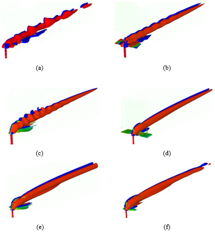
In Fig. (4 ), the overall view of the three dimensional vortex structures for the JICF after full development at Re=100 are shown. Large scale structures nested within each other in the figures demonstrate the existence of large scale vortices including CRVP, RLV, WV and shear layer vortices, etc. After full evolution for the JICF, the vortex structure in the JICF is dominated by the CRVP and RLV, which is twisted on the CRVP. Small scale structure of the jet in the vital area can generate the ongoing of the tension and crush due to the interaction between the JICF and the shear layer. The RLV is gradually decomposed into the crossflow far away from the entrance of the jet.
In the JICF without block at various r shown in Fig. (4a, c and e), it is apparent that the stable and mixed vortex structures including the CRVP, RLV, WV and UV are generated from the nozzle. The mixed vortex structures are constantly stretching and rupturing with the increasing distance in the streamwise direction, and the vortices are merged into the crossflow. The gap between the mixed vortex structures is declined as the velocity ratio increases. Fig. (4b, d and f) for the JICF with block indicate that the magnitude of the mixed vortices formed near the jet nozzle is clearly weakened under the influence of the block. And the affected vortices are further mixed in the crossflow. Compared with the JICF with and without block, the presence of the block can accelerate the forming of the stable CRVP, which is more apparent at low velocity ratio.
In Fig. (4a, c and e), the forming frequency of the RLV increases as the velocity ratio augments, and the corresponding gap between the RLV decreases. Far away from the jet nozzle, the intensity of the mixed vortices including RLV is declining. At higher velocity ratio r=3, the compact RLV is generated near the jet nozzle due to the higher momentum. Nevertheless, owing to the strong interaction of the UV, CRVP and shear layer, the RLV disappears soon. In the JICF with block at low velocity ratio r=1, the RLV broken by the block can not be generated again after full development of the JICF. However, at higher r (r=3) in Fig. (4f), even if affected by the block, the RLV in the JICF with block can still generate a stable performance, and the intensity has been significantly receded.
Analysis of the Spanwise Vorticity
In the initial stage of the evolution for the JICF, large scale vortex structures still contain CRVP and RLV near the vicinity of the jet field entrance. In Fig. (5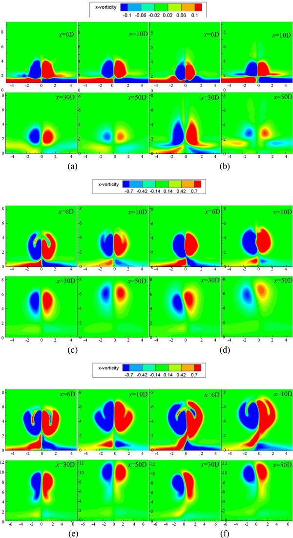 ), the small scale vortex structures can be clearly seen, such as UV and WV. During the development, the CRVP remains a substantially symmetrical shape. And a few new vortices are generated in the full evolution of the JICF owing to the enhanced interaction between the UV and WV. On the leeward side of the JICF, a turbulence wake shakes off along the trail, which is similar to Karman vortex street. The interaction between the turbulence wake and the CRVP not only can generate an oscillation for the CRVP along the streamwise direction, but it also can lift the CRVP up, which is counter rotating around the jet axis.
Fig. (5) show the typical instantaneous flow patterns of the spanwise vortices for the JICF with and without block at various position, in which all the flow time is fixed at 60 seconds after the JICF starts. In Fig. (5), the positive vortices are mainly located on the right side, the negative vortices are on the left, respectively. As shown in the Fig. (5b) for the JICF with block at r=1, the mixed vortices affected by the block generate a preliminary change. Due to the lower momentum, the JICF with block has not been completely aggregated in the Fig. (5b) at x=6D in the streamwise direction, and a small amount of JICF fluids are still above the mixed vortices, which is different by comparing with the Fig. (5a). With the continuous evolution of the JICF, the mixed vortex structures are more compact under the effect of the block and the vigorous detour flow in the JICF (x=10D and x=30D in Fig. (5a). The CRVP can generate a rising height and the corresponding intensity of the vortices is declined with the increasing distance from the jet nozzle. This means that the internal flow in the JICF is generating a stable performance. It is also found that in Fig. (5a and b) at r=1, the CRVP has generated a rudiment of the kidney-shaped vortices in the both JICF with and without block. And at low velocity ratio, the kidney-shaped vortices gradually become regular and substantially symmetrical during the development of the JICF.
As the velocity ratio increases, the mixed vortices affected by the block are different from those at r=1. Fig. (5c-f) demonstrate that the mixed positive and negative vortices are not symmetrical any more at higher velocity ratio (r=2 and r=3). The magnitude of positive vortices is larger than the negative ones, which is more apparent with the progress of the JICF. This is due to the mixing and merging impact of the jets destroyed by the block. In the flow patterns, there is some enhanced coupling between the positive and negative vortex structures, as the r increases, the coupling is enhanced. The distance between the positive and negative vortex structure of the JICF without block is very small in Fig. (5e ) at r=3, which is not obvious at low velocity ratio. This phenomenon indicates that the unstable performance of the JICF is closely related to the velocity ratio. Moreover, as displayed in Fig. (5f), there is obvious coupling between the positive and negative vortex structures in the JICF with block at the same velocity ratio and location. This indicates that the existence of the block has strengthened the coupling effect between the positive and negative vortex structures.

Temperature Field
In order to facilitate the study of temperature field, He [22He, G.; Guo, Y.; Hsu, A.T. The effect of Schmidt number on turbulent scalar mixing in a jet-in-crossflow. Int. J. Heat Mass Transfer, 1999, 42(20), 3727-3738.
[http://dx.doi.org/10.1016/S0017-9310(99)00050-2] ] had non-dimensionalized the temperature in the JICF as:
 |
(10) |
where Tj is the temperature of jet, Tcf is the crossflow, respectively. The temperature field on the iso-surface for the compared cases for the identical velocity ratio (r=3) are displayed in Fig. (6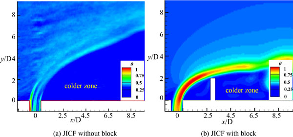 ).
).
In the Fig. (6), the colder zone is located on the leeward side of the jet in the near field. The compared results show that the performance of the temperature field for the JICF with and without block is different. As indicated in Fig. (6a), the windward side of the jet is elusive and the height of the temperature contours is higher. However, in Fig. (6b), owing to the effect of the block on velocity profile, the temperature field of the JICF with block has shown a lower height, and the corresponding colder zone generates a smaller area than the JICF without block. It is apparent that the block has a significant effect on the temperature field. This means that the block effectively decreases the colder zone in the JICF, which may be applied to the film cooling of turbines and combustors. While as exhibited in Fig. (6), the total energy of the JICF with block is higher than the JICF without block, which is because of the excitation effect from the block.
 |
Fig. (6) Temperature field on the iso-surface at r=3. |
CONCLUSION
Large eddy simulation of the jet in crossflow at very low Reynolds number (Re=100) with and without block is conducted, while the range of the corresponding velocity ratios (r) is from 1 to 3. The flow characteristics for the both results are compared, and the conclusions are listed as follows:
(1) With the increasing of the velocity ratio, the penetration of the JICF is deeper. The difference of the time-averaged particle trajectories between the JICF with and without block is small, but the block has an impact on the penetration and stability.
(2) The stable and mixed vortex structure including the CRVP, RLV, WV and UV are generated from the nozzle. As the velocity ratio augments, the magnitude of the mixed vortices affected by the block is declined, and the forming frequency of the RLV increases. At low velocity ratio, the RLV in the JICF with block disappears soon. At high velocity ratio, the RLV affected by the block in the JICF with block can still generate a stable performance near the nozzle, but the intensity is significantly decreasing.
(3) At low velocity ratio (r=1), the kidney-shaped vortices remain substantially symmetrical. However, with the increasing of the velocity ratio, the mixed positive and negative vortices in the JICF with block are not symmetrical any more. The existence of the block has strengthened the coupling effect between the positive and negative vortex structures. The block decreases the colder zone effectively in the temperature field, and the total energy of the JICF with block is higher than the JICF without block.
CONFLICT OF INTEREST
The authors confirm that this article content has no conflict of interest.
ACKNOWLEDGEMENTS
The grant support from the National Science Foundation of China (No. U1430113) and Academic Start Program for Young Teachers of Beijing Institute of Technology (No. 3010012261502) is greatly acknowledged.
REFERENCES
| [1] | Muppidi, S.; Mahesh, K. Direct numerical simulation of round turbulent jets in crossflow. J. Fluid Mech., 2007, 574, 59-84. [http://dx.doi.org/10.1017/S0022112006004034] |
| [2] | Campolo, M.; Salvetti, M.V.; Soldati, A. Mechanisms for microparticle dispersion in a jet in crossflow. AlChE J., 2005, 51(1), 28-43. [http://dx.doi.org/10.1002/aic.10301] |
| [3] | Kawai, S.; Lele, S.K. Large-eddy simulation of jet mixing in supersonic crossflows. AIAA J., 2010, 48(9), 2063-2083. [http://dx.doi.org/10.2514/1.J050282] |
| [4] | Rana, Z.A.; Thornber, B.; Drikakis, D. Transverse jet injection into a supersonic turbulent cross-flow. Phys. Fluids, 2011, 23(4), 046103. [http://dx.doi.org/10.1063/1.3570692] |
| [5] | Majander, P.; Siikonen, T. Large-eddy simulation of a round jet in a cross-flow. Int. J. Heat Fluid Flow, 2006, 27(3), 402-415. [http://dx.doi.org/10.1016/j.ijheatfluidflow.2006.01.004] |
| [6] | Mendez, S.; Nicoud, F. Large-eddy simulation of a bi-periodic turbulent flow with effusion. J. Fluid Mech., 2008, 598, 27-65. [http://dx.doi.org/10.1017/S0022112007009664] |
| [7] | Ben-Yakar, A.; Mungal, M.G.; Hanson, R.K. Time evolution and mixing characteristics of hydrogen and ethylene transverse jets in supersonic crossflows. Phys. Fluids, 2006, 18(2), 026101. [http://dx.doi.org/10.1063/1.2139684] |
| [8] | Viti, V.; Neel, R.; Schetz, J.A. Detailed flow physics of the supersonic jet interaction flow field. Phys. Fluids, 2009, 21(4), 046101. [http://dx.doi.org/10.1063/1.3112736] |
| [9] | Camussi, R.; Guj, G.; Stella, A. Experimental study of a jet in a crossflow at very low Reynolds number. J. Fluid Mech., 2002, 454, 113-144. [http://dx.doi.org/10.1017/S0022112001007005] |
| [10] | Salewski, M.; Stankovic, D.; Fuchs, L. Mixing in circular and non-circular jets in crossflow. . Flow Turbul. Combus., 2008, 80(2), 255-283. [http://dx.doi.org/10.1007/s10494-007-9119-x] |
| [11] | Cárdenas, C.; Denev, J.A.; Suntz, R.; Bockhorn, H. Study of parameters and entrainment of a jet in cross-flow arrangement with transition at two low Reynolds numbers. Exp. Fluids, 2012, 53(4), 965-987. [http://dx.doi.org/10.1007/s00348-012-1333-1] |
| [12] | Yuan, L.L.; Street, R.L.; Ferziger, J.H. Large-eddy simulations of a round jet in crossflow. J. Fluid Mech., 1999, 379, 71-104. [http://dx.doi.org/10.1017/S0022112098003346] |
| [13] | Cárdenas, C.; Suntz, R.; Denev, J.A.; Bockhorn, H. Two-dimensional estimation of Reynolds-fluxes and-stresses in a Jet-in-Crossflow arrangement by simultaneous 2D-LIF and PIV. Appl. Phys. B, 2007, 88(4), 581-591. [http://dx.doi.org/10.1007/s00340-007-2734-3] |
| [14] | Muppidi, S.; Mahesh, K. Study of trajectories of jets in crossflow using direct numerical simulations. J. Fluid Mech., 2005, 530, 81-100. [http://dx.doi.org/10.1017/S0022112005003514] |
| [15] | Computional Bridge Aerodynamics Large Eddy Simulation; China Communications Press: Beijing, 2010. |
| [16] | Chassaing, P.; George, J.; Claria, A.; Sananes, F. Physical characteristics of subsonic jets in a cross-stream. J. Fluid Mech., 1974, 62(1), 41-64. [http://dx.doi.org/10.1017/S0022112074000577] |
| [17] | Pratte, B.D.; Baines, W.D. Profiles of the round turbulent jet in a cross flow. J. Hydraul. Eng., 1967, 93(6), 53-64. |
| [18] | New, T.H. Near-field developments of elliptic jets in crossflow. J. Turbul., 2008, 9, 1-21. [http://dx.doi.org/10.1080/14685240802195177] |
| [19] | Bagheri, S.; Schlatter, P.; Schmid, P.J.; Henningson, D.S. Global stability of a jet in crossflow. J. Fluid Mech., 2009, 624, 33-44. [http://dx.doi.org/10.1017/S0022112009006053] |
| [20] | Zhang, G.Q.; Yu, S.C.; Chien, A.; Yang, S.X. Aerodynamic characteristics of canard-forward swept wing aircraft configurations. J. Aircr., 2013, 50(2), 378-387. [http://dx.doi.org/10.2514/1.C031740] |
| [21] | Gutmark, E.J.; Grinstein, F.F. Flow control with noncircular jets. . Annu. Rev. Fluid Mech., 1999, 31(1), 239-272. [http://dx.doi.org/10.1146/annurev.fluid.31.1.239] |
| [22] | He, G.; Guo, Y.; Hsu, A.T. The effect of Schmidt number on turbulent scalar mixing in a jet-in-crossflow. Int. J. Heat Mass Transfer, 1999, 42(20), 3727-3738. [http://dx.doi.org/10.1016/S0017-9310(99)00050-2] |