- Home
- About Journals
-
Information for Authors/ReviewersEditorial Policies
Publication Fee
Publication Cycle - Process Flowchart
Online Manuscript Submission and Tracking System
Publishing Ethics and Rectitude
Authorship
Author Benefits
Reviewer Guidelines
Guest Editor Guidelines
Peer Review Workflow
Quick Track Option
Copyediting Services
Bentham Open Membership
Bentham Open Advisory Board
Archiving Policies
Fabricating and Stating False Information
Post Publication Discussions and Corrections
Editorial Management
Advertise With Us
Funding Agencies
Rate List
Kudos
General FAQs
Special Fee Waivers and Discounts
- Contact
- Help
- About Us
- Search


The Open Mechanical Engineering Journal
(Discontinued)
ISSN: 1874-155X ― Volume 14, 2020
Simplified and Accurate Stiffness of a Prismatic Anisotropic Thin-Walled Box
Giacomo Canale1, *, Felice Rubino2, Paul M. Weaver3, Roberto Citarella2, Angelo Maligno4
Abstract
Background:
Beam models have been proven effective in the preliminary analysis and design of aerospace structures. Accurate cross sectional stiffness constants are however needed, especially when dealing with bending, torsion and bend-twist coupling deformations. Several models have been proposed in the literature, even recently, but a lack of precision may be found when dealing with a high level of anisotropy and different lay-ups.
Objective:
A simplified analytical model is proposed to evaluate bending and torsional stiffness of a prismatic, anisotropic, thin-walled box. The proposed model is an extension of the model proposed by Lemanski and Weaver for the evaluation of the bend-twist coupling constant.
Methods:
Bending and torsional stiffness are derived analytically by using physical reasoning and by applying bending and torsional stiffness mathematic definition. Unitary deformations have been applied when evaluation forces and moments arising on the cross section.
Results:
Good accuracy has been obtained for structures with different geometries and lay-ups. The model has been validated with respect to finite element analysis. Numerical results are commented upon and compared with other models presented in literature.
Conclusion:
For cross sections with a high level of anisotropy, the accuracy of the proposed formulation is within 2% for bending stiffness and 6% for torsional stiffness. The percentage of error is further reduced for more realistic geometries and lay-ups.
The proposed formulation gives accurate results for different dimensions and length rations of horizontal and vertical walls.
Article Information

Identifiers and Pagination:
Year: 2018Volume: 12
First Page: 1
Last Page: 20
Publisher Id: TOMEJ-12-1
DOI: 10.2174/1874155X01812010001
Article History:
Received Date: 11/10/2017Revision Received Date: 20/12/2017
Acceptance Date: 29/12/2017
Electronic publication date: 14/02/2018
Collection year: 2018
open-access license: This is an open access article distributed under the terms of the Creative Commons Attribution 4.0 International Public License (CC-BY 4.0), a copy of which is available at: (https://creativecommons.org/licenses/by/4.0/legalcode). This license permits unrestricted use, distribution, and reproduction in any medium, provided the original author and source are credited.
* Address correspondence to this author at the Rolls-Royce plc, Department of Aerospace Engineering, Moor Lane, Derby, DE24 8BJ, UK, Tel: +44 (0) 1332 2 49885; E-mail: giacomo.canale@rolls_royce.com
| Open Peer Review Details | |||
|---|---|---|---|
| Manuscript submitted on 11-10-2017 |
Original Manuscript | Simplified and Accurate Stiffness of a Prismatic Anisotropic Thin-Walled Box | |
1. INTRODUCTION
Beam models have proven themselves to be effective in a variety of engineering structures. In aeroelastic studies, for example, beam models have been used to reveal important trends and generally, rectangular or trapeze cross sections have been used to model wing boxes [1T.A. Weisshaar, C. Nam, and A. Baptista-Rodriguez, "Aeroelastic Tailoring for Improved UAV Performance", AIAA Paper 98-1757. Presented at the 39th AIAA/ASME/ASCE/AHS/ASC Structures, Structural Dynamics, and Materials Conference American Institute of Aeronautics and Astronautics Long Beach, California, pp. 20-23.
[http://dx.doi.org/10.2514/6.1998-1757] -4W. Dengfeng, Y. Yongfu, P. Licheng, and D. Haijin, "Study of Load Bearing Capacity of Profiled Steel Sheet Wall Subjected to Combined Bending and Vertical Compression in Electrostatic Precipitator", Open Mech. Eng. J., vol. 8, pp. 326-331.
[http://dx.doi.org/10.2174/1874155X01408010326] ].
One example of prismatic thin-walled box of rectangular cross section is shown in Fig. (1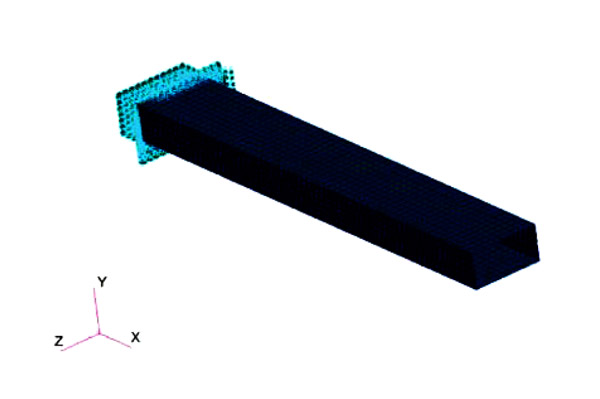 ). Its global coordinate system, shown in Fig. (2
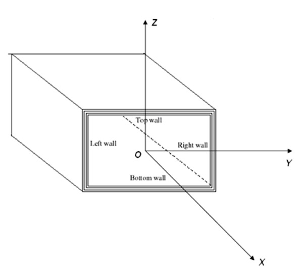 ), is denoted with letters X, Y, Z, and it can be located in any point of the cross section. The origin of the frame is denoted by the letter O.
 |
Fig. (1) An example of prismatic thin-walled composite box. |
 |
Fig. (2) The global frame X, Y, Z of the box. |
For aeroelastic purposes, the structures analysed are often slender and long, so that three essential stiffness constants are required to evaluate the deformations. As suggested by Weisshaar [5T.A. Weisshaar, "Aeroelastic Tailoring-Creative use of unusual materials", 28th proceeding AIAA/ASME/ASCE/AHS/ASC Structural Dynamics and Materials Conference, American Institute of Aeronautics and Astronautics: Monterey, California, .], at any cross section along the reference x-axis of the beam, a linear equation describes the structural behaviour:
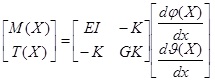 |
(1) |
where:
EI the bending stiffness [Nm2]
GK the torsional stiffness [Nm2]
K the bend-twist coupling stiffness [Nm2]
M(X) the bending moment at the span wise coordinate x [Nm]
T(X) the twisting moment at the span wise coordinate x [Nm]
X the span wise coordinate along the main dimension of the beam [m]
ϑ(X) the twisting angle at the span wise coordinate x [m-1]
φ(X) the flexural angle and the span wise coordinate x [m-1]
Once the internal loads M(X) and T(X) are calculated from the external distribution of forces and moments, Eq. 1 can be inverted and the deformation of the beam can be evaluated.
In order to obtain appropriate deformations, the evaluation of stiffness EI, GK and K must be as accurate as possible. A correct evaluation of the stiffness parameters of a composite beam is not a trivial problem as confirmed by the number of different formulations presented in literature [6L.W. Rehfield, A.R. Atilgan, and D.H. Hodges, "Nonclassical behaviour of thin-walled composite beams with closed cross-sections", J. Am. Helicopter Soc., vol. 35, no. 2, pp. 42-50.
[http://dx.doi.org/10.4050/JAHS.35.42] -15E. Carrera, M. Filippi, P.K. Mahato, and A. Pagani, "Accurate static response of single and multi-cell laminated box beams", Compos. Struct., vol. 136, pp. 372-383.
[http://dx.doi.org/10.1016/j.compstruct.2015.10.020] ]. Such models often show a lack of precision when cross sections with different geometries (even simple rectangular cross sections) and unbalanced lay-ups are analysed. This effect is more accentuated when a high level of anisotropy exists. It is the case of reinforcements made by fibres with the same orientation.
Concerning bend-twist coupling stiffness, K, the analytical predictions of Lemanski and Weaver [12S.L. Lemanski, and P.M. Weaver, "Flap-torsion coupling in sandwich beams and filled box sections", Thin-walled Struct., vol. 43, no. 6, pp. 923-955.
[http://dx.doi.org/10.1016/j.tws.2004.12.004] ] is relatively accurate, simple and based on physical reasoning. Their results have been investigated and reproduced as part of this work. Examples, in fact, are shown in section 3. No further discussion on the stiffness K is therefore provided.
The same cannot be said for bending and torsional stiffness, since formulae presented in the literature are not able to provide sufficient accuracy when cross sections of different geometries and lay-ups are analysed. Therefore, models able to predict accurate results are required.
The approach used by Lemanski and Weaver to calculate K is extended in this paper to evaluate the bending stiffness EI of a symmetric composite thin-walled box. A new analytical formula is also proposed to evaluate GK.
2. ANALYTICAL MODELS
2.1. Evaluation of EI
The strategy used by Lemanski and Weaver to evaluate bend-twist coupling stiffness K is now extended to the evaluation of the bending stiffness EI.
The key point is the definition of the stiffness K: it is the twisting moment arising in a cross section when a unitary bending curvature
 is applied.
When a unitary bending curvature
 is applied, (without twisting, i.e.
 a torsional moment is obtained from Eq. 1 as:
 |
(2) |
The numerical value of the stiffness therefore coincides with the twisting moment arising in the walls of the cross section. Similar reasoning can be used to evaluate EI: as the bending moment arising in the cross section when the same unitary bending deformation is applied.
Consider a hollow box shown in Fig. (3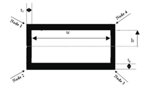 ).
).
The box is symmetrical, such that the top and bottom laminates are identical. Moreover, the vertical walls are made by balanced laminates, as unbalanced laminates are not necessary to induce bend-twist coupling of the box. Let us denote its geometrical characteristics by:
w the length of the horizontal wall [m]
2h the length of the vertical wall [m]
ty the thickness of the vertical wall [m]
th the thickness of the horizontal wall [m]
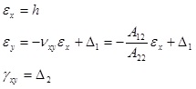
Now apply a unitary bending deformation.
 On the top wall of the box, if the material is orthotropic and the stiffness of vertical walls negligible, then strains would be [10L.P. Kollar, and A. Pluzsik, "Analysis of thin-walled composite beams with arbitrary layup", J. Reinf. Plast. Compos., vol. 21, no. 16, pp. 1423-1465.
[http://dx.doi.org/10.1177/0731684402021016928] ]:
 |
(3) |
Where:
εx axial strain
εxy transversal strain
Vxy shear strain
νxy Poisson’s ratio of composite laminate
 |
Fig. (3) Geometric characteristics of a box cross section. |
The strains of Eq. 3 are written with respect to the local coordinates x, y of the laminate, shown in Fig. (4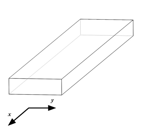 ).
).
 |
Fig. (4) Local coordinates in a laminate wall. |
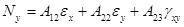
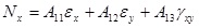
The forces per unit of length corresponding to these strains are:
Nx axial force per unit of length of horizontal laminate
Ny lateral forces per unit of length of horizontal laminate
Nxy shear force per unit of length of horizontal laminate
they are evaluated by using Classical Lamination Theory [16Z. Gurdal, R.T. Haftka, and P. Hajela, Design and optimization of Laminated composite materials., Wiley Interscience: New York, .]. As the box is made of laminated composite materials and the presence of vertical walls constrains the deformation of horizontal laminate, the strain field, Eq. 3, requires modification.
Two corrective terms Δ1 and Δ2 are added for the following reasons:
- Lateral deformation εy of the horizontal laminate is constrained by the vertical walls and depends not only on the characteristics of the laminate itself but also on the elastic properties of the vertical walls.
- Shear deformation γxy of the laminate is present; otherwise no bend/twist coupling effect exists.
The strain field of the horizontal laminate is re-written as
 |
(4) |
where Aij is the membrane constants of the top laminate. The terms Δ1 and Δ2 are unknown. Two algebraic equations are needed to determine them. The first equation can be written evaluating displacement δ of Node 1, shown in Fig. (5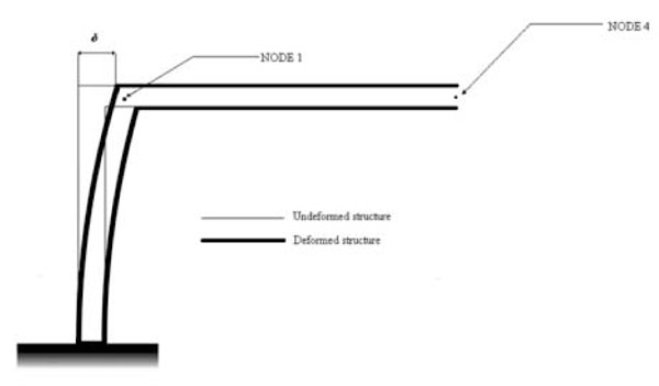 ).
).
Node 1 can be thought as a part of the horizontal laminate. Therefore, the displacement δ can be written as
 |
(5) |
 |
Fig. (5) Displacement δ of Node 1. |
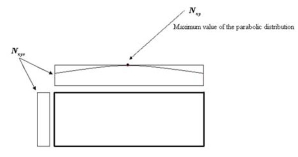 |
Fig. (6) An idealization of the deflection of the vertical wall. |
On the other hand, Node 1 is also part of the vertical wall. Its deflection can be calculated by modelling half of the vertical wall as a cantilevered beam (Fig. 6 ), as suggested by Lemanski and Weaver [12S.L. Lemanski, and P.M. Weaver, "Flap-torsion coupling in sandwich beams and filled box sections", Thin-walled Struct., vol. 43, no. 6, pp. 923-955.
[http://dx.doi.org/10.1016/j.tws.2004.12.004] ]. The displacement, δ, is that of a cantilever beam [14C. Zhang, and S. Wang, "Structure mechanical modelling of thin walled closed section composite beams, Part 1: Single cell cross section", Compos. Struct., vol. 113, pp. 12-22.
[http://dx.doi.org/10.1016/j.compstruct.2014.03.005] ]:
 |
(6) |
where Ny is found directly from Classical Lamination Theory,
 |
(7) |
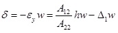
If Eq. 7 is substituted in to Eq. 6 and combined with Eq. 5, then:
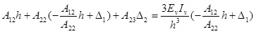 |
(8) |
The second expression can be deduced from the equilibrium of tangential forces, as suggested in reference [10L.P. Kollar, and A. Pluzsik, "Analysis of thin-walled composite beams with arbitrary layup", J. Reinf. Plast. Compos., vol. 21, no. 16, pp. 1423-1465.
[http://dx.doi.org/10.1177/0731684402021016928] ]:
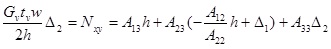 |
(9) |
where Gv is the shear modulus of the vertical wall.
An algebraic system comprising two equations (Eq. 8 and 9) in two unknowns Δ1 and Δ2 is obtained and is readily solved. Once Δ1 and Δ2 are calculated, they are substituted in to Eq. 4 and the strain field of the top laminate is completely defined.
Concerning vertical walls, their local coordinates xv, yv are shown in Fig. (7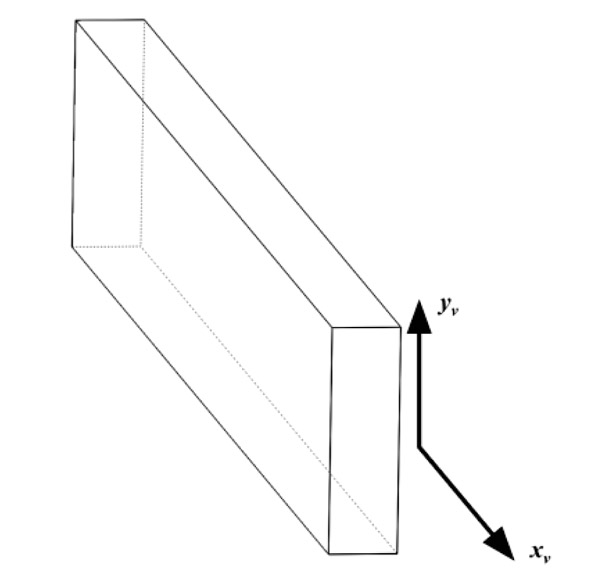 ).
).
 |
Fig. (7) Local coordinates of vertical walls. |
Consequently, xv and x, are coincident and they have the same direction of the global axis X. Forces per unit of length of vertical walls are:
Nxv the axial force per unit of length.
Nvv the lateral force per unit of length
Nxvy is the shear force per unit of length
While corresponding strains are given by:
εxv the axial strain
εvv the lateral strain
γxvy the shear deformation
As EI is the bending moment arising in the cross section when a unitary bending curvature is applied, it can be calculated as the bending moment with respect to the global Y axis,
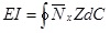 |
(10) |
Where:
dC the infinitesimal element of the contour
 the axial force per unit of length in the global reference. It includes contributions from both Nx and Nxv.
Eq. 10 can be divided into two components, those from the horizontal and vertical walls. The contribution from the top and bottom laminates is:
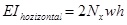 |
(11) |
Where:
 |
(12) |
And the strains of Eq. 12 are found from Eq. 4.
Now consider half of the vertical wall, in order to evaluate the second component. The strain εxv, for simple bending, is a linear function of the global coordinate Z:
εxv = Z
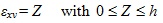 |
(13) |
The contribution of the vertical walls to the bending stiffness is, consequently:
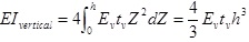 |
(14) |
where tv is the thickness of vertical walls. The final expression of bending stiffness EI is:
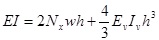 |
(15) |
2.2. Evaluation of Torsional Stiffness GK
In this section, a model to predict the torsional stiffness GK is presented. The starting point is the formula developed by Librescu and Song [7L. Librescu, and O. Song, "On the static aeroelastic tailoring of composite aircraft swept wings modelled as thin-walled beam structures", Compos. Eng., vol. 2, no. 5-7, pp. 497-512.
[http://dx.doi.org/10.1016/0961-9526(92)90039-9] ]. It has been chosen among several formulations because it shows two good characteristics:
- It is quite accurate, especially if compared to the other models investigated.
- Its formulation is relatively straightforward.
Other models, such as that due to Kollar and Pluzsik [10L.P. Kollar, and A. Pluzsik, "Analysis of thin-walled composite beams with arbitrary layup", J. Reinf. Plast. Compos., vol. 21, no. 16, pp. 1423-1465.
[http://dx.doi.org/10.1177/0731684402021016928] ], for example, contain more information and are more involved to implement.
The initial formula proposed by Librescu and Song can be re-arranged as follows:
 |
(16) |
Where:
Aijv the terms of the membrane matrix of the vertical wall
Ω the area enclosed by the contour of the cross section
 |
(17) |
There are two contributions to the torsional stiffness:
- the contribution given by the vertical walls:
- the contribution given by the top and bottom laminates:
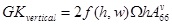 |
(18) |
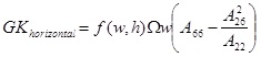 |
(19) |
Using Lemanski and Weaver’s approach, the stiffness GK can be thought as the twisting moment arising in a cross section when a unitary twisting curvature is applied. The forces per unit of length arising on the vertical and horizontal walls are derived from Eq.16, as
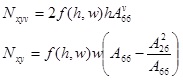 |
(20) |
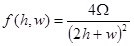
To ensure dimensional accuracy, forces per unit length in Eq. 20 should be divided by
. These forces per unit of length are usually not equal and they are constant along the walls. This fact implies a discontinuity of the tangential forces per unit of length at the corners of the cross sections, as shown in the example of Fig. (8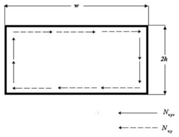 ).
).
 |
Fig. (8) Discontinuity of tangential forces in the model of Librescu and Song. |
The shear continuity at the corners is imposed by assuming a parabolic distribution in the horizontal laminates, of force per unit of length, with the maximum value between Nxyv and Nxy. For example, when Nxy is greater than Nxyv, the shear flow of the top/bottom laminate will be assumed to vary parabolically: Its value at the corner will be equal to Nxyv, and its maximum value, at the middle point of the wall, will be equal to Nxy (Fig. 9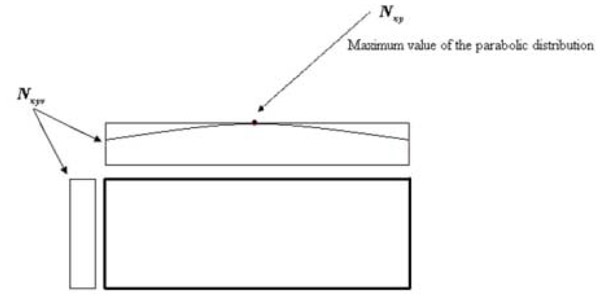 ). In other words, the shear flow of the horizontal laminates is now a parabolic function Nxy(y), where y is the local axis of the laminate, shown in Fig. (4). An analogous distribution occurs when Nxyv is greater than Nxy. In this case, the shear flow of the vertical laminates is assumed to vary parabolically. The average shear flow in the horizontal laminate is
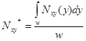 |
(21) |
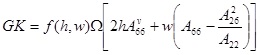
The stiffness GK can be therefore evaluated with Bredt’s formula [17 Pitagora Ed. Erasmo Viola, Theory of Constructions, Theory of Elasticity, Vol. 1 , 1990, p. 628. ISBN: 978-8837104931]:
 |
(22) |
Where N is an average expression of the shear flow along all the contour found from
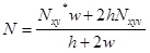 |
(23) |
This formulation provides excellent results for rectangular geometries and it can be easily extended to the trapeze cross sections, as it will be shown in the section 3.2.
 |
Fig. (9) Parabolic correction of Nxy (in red) on the Librescu formulation (in black). |
3. RESULTS
Two different cross-sections have been analysed. The first one is with rectangular shape. Even if the geometry is simple, to the authors’ knowledge the analytical model proposed in this paper is the only one providing good accuracy for structures with high level of anisotropy. The second one is a trapeze cross section, with realistic laminates. It has been analysed to show that the model is able to provide good results with more realistic structures.
3.1. Rectangular Cross Section
Three rectangular cross sections representing three different boxes, have been analyzed. Top and bottom laminates are made with one single layer whose fibres orientation α can vary from 0 to 90 degrees with respect to the local frame represented in Fig. (4). This assumption has been made to maximise the effects of anisotropy. Vertical walls are orthotropic. They are made with one single layer with fibres oriented at 0 degrees. Appropriate elastic properties for both vertical and horizontal laminates are:
E1 = 181 GPa
E2 = 10.3 GPa
G12 = 4.55 GPa
ν12 = 0.28
Elastic properties of α- oriented laminates are calculated by using the constants reported above and the classical lamination theory.
These three cross sections have different wall lengths, but the same shape and the same area enclosed by the contour. Data are reported in Table 1.
Finite element analysis (FE) using Patran/Nastran [18 MSC software, MSC Nastran 2016. Newport Beach, CA, 2016. Available from: http://documents.mscsoftware.com/ sites/default/files/ro_nastran-2016_ltr_w.pdf] was performed to validate the results. The displacements and rotations are set to zero on one side of the beam whilst MPC of type RBE2 have been used to apply the end tip loads as shown in Fig. (10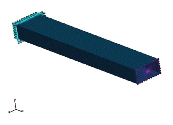 ).
).
 |
Fig. (10) An example of FE model used to validate the analytical results. |
The following steps were done to obtain bending and torsional stiffness.
- A unitary bending moment is applied to the tip of the beam.
- Bending and twisting deformations are measured in a cross section located at the middle span of the beam: Sufficiently far from the tip and root, in order to avoid the effects of local deformations. The ensuing bending and twisting deformations, due to a unitary bending moment, represent bending and bend/twist coupling compliances (Eq. 1).
- A unitary twisting moment is applied to the tip of the wing with no bending moment.
- Twisting deformation is measured and consequently twisting compliance.
- Once all the compliances are known, they can be inverted. The inverse of the compliance matrix is the stiffness matrix of Eq.1.
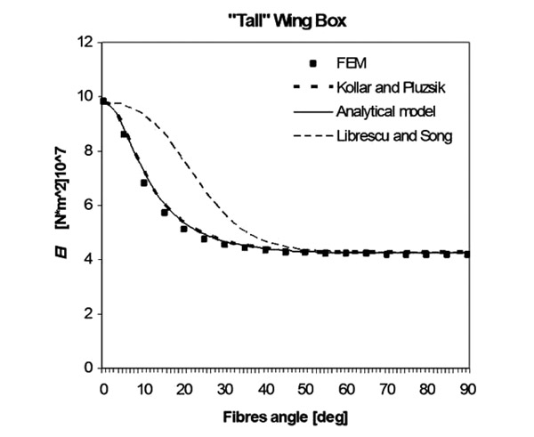 |
Fig. (11) EI for the “Tall” unbalanced composite wing box. Fibres angle vary from 0 to 90 degrees. |
Results for EI of unbalanced boxes are shown in Figs. (11 -13
-13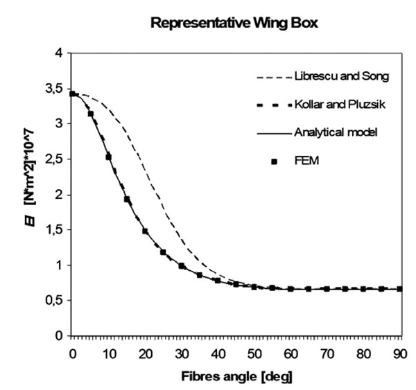 ). The analytical model presented in this paper has been compared with two other different models (Kollar and Pluzsik theory [10L.P. Kollar, and A. Pluzsik, "Analysis of thin-walled composite beams with arbitrary layup", J. Reinf. Plast. Compos., vol. 21, no. 16, pp. 1423-1465.
[http://dx.doi.org/10.1177/0731684402021016928] ] and Librescu and Song’s theory [7L. Librescu, and O. Song, "On the static aeroelastic tailoring of composite aircraft swept wings modelled as thin-walled beam structures", Compos. Eng., vol. 2, no. 5-7, pp. 497-512.
[http://dx.doi.org/10.1016/0961-9526(92)90039-9] ] and also with FE.
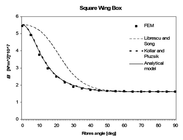 |
Fig. (12) EI for the “Square” unbalanced composite wing box. Fibres angle vary from 0 to 90 degrees. |
 |
Fig. (13) EI for the “Representative” unbalanced composite wing box. Fibres angle vary from 0 to 90 degrees. |
The analytical model is shown to be accurate and it gives approximately the same results as Kollar and Pluzsik theory, but its formulation is simpler.
The model has also been tested with structures whose top and bottom walls are made of balanced composite materials (laminates with + α and -α fibres). Results obtained for the square wing box are shown in Fig. (14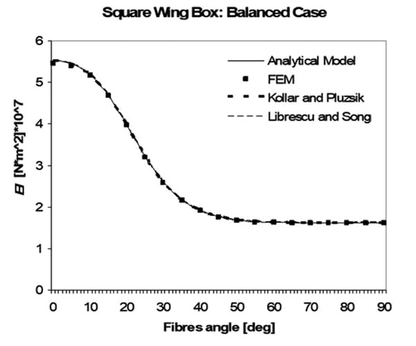 ). In this case, all the models give approximately the same results.
 |
Fig. (14) EI for the “Square” balanced composite wing box. Fibres angle vary from 0 to 90 degrees. |
Results for the evaluation of GK have also been produced. The new formulation has been compared with the models of Librescu and Song and Kollar and Pluzsik, respectively Figs. (15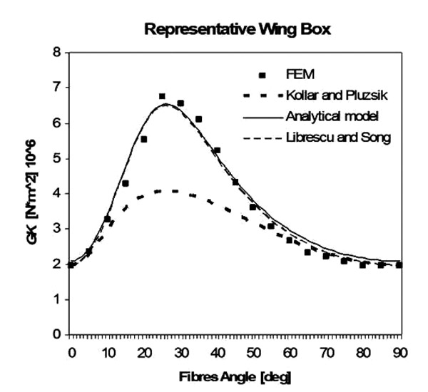 -17
-17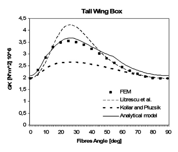 ). It is evident that the model proposed in this paper is the only one (to our knowledge) which works sufficiently well for all three different geometries.
 |
Fig. (15) GK for the “representative” unbalanced composite wing box. Fibres angle vary from 0 to 90 degrees. |
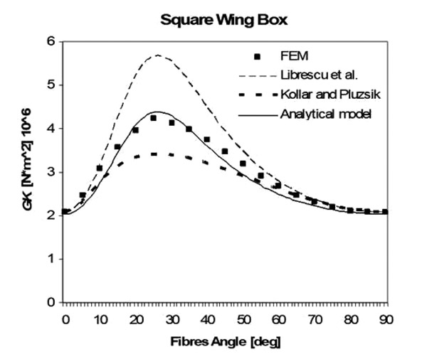 |
Fig. (16) GK for the “square” unbalanced composite wing box. Fibres angle vary from 0 to 90 degrees. |
 |
Fig. (17) GK for the “square” unbalanced composite wing box. Fibres angle vary from 0 to 90 degrees. |
The main reason lies on the fact that the proposed way to calculate stiffness is based on its physical meaning (deformation under unitary loads) rather than the integration of stiffness along the segments of the cross section (furthermore Librescu’s models offer a slightly simpler formulation compared to Kollar’s model and the results could be slightly less accurate when dealing with high level of anisotropy).
Concerning bend/twist coupling stiffness K, good results have been obtained by using Lemanski-Weaver's model [12S.L. Lemanski, and P.M. Weaver, "Flap-torsion coupling in sandwich beams and filled box sections", Thin-walled Struct., vol. 43, no. 6, pp. 923-955.
[http://dx.doi.org/10.1016/j.tws.2004.12.004] ]. The development of a new theory is therefore not needed. In Figs. (18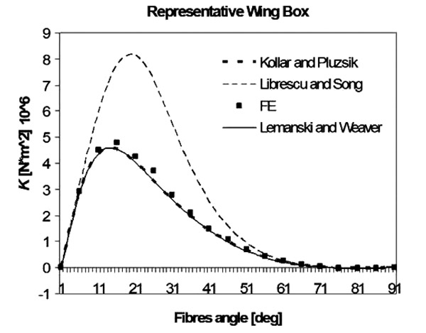 -20
-20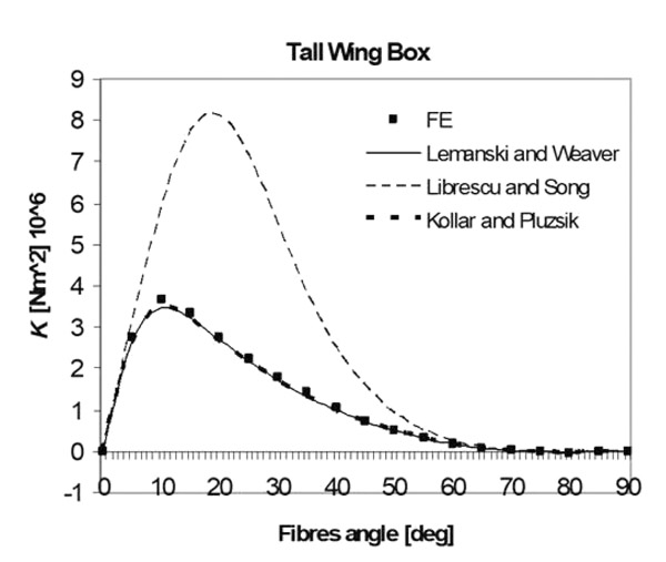 ), a study case on boxes described in Table 1 is shown. The models of Lemanski-Weaver and Kollar-Pluzsik have the same level of accuracy, but the implementation of the model of Lemanski and Weaver, also in this case, is simpler.
 |
Fig. (18) Bend/twist coupling stiffness K for a representative wing box. |
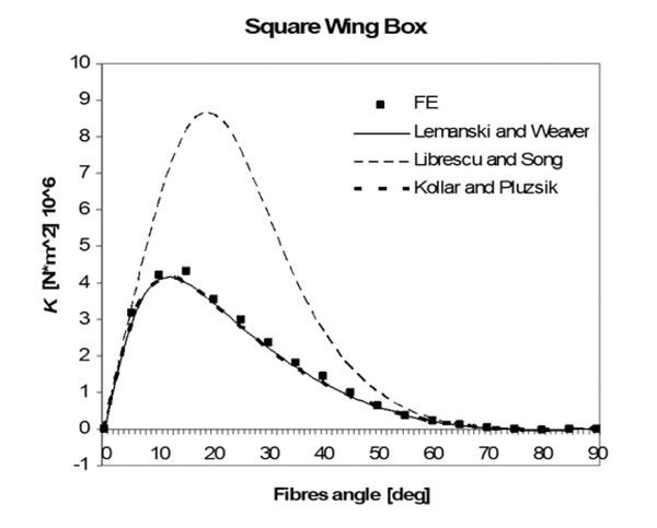 |
Fig. (19) Bend twist coupling stiffness K for a square wing box. |
 |
Fig. (20) Bend twist coupling stiffness K for the “tall” wing box. |
3.2. Trapeze Cross Section
A more complex geometry is studied in this section. Rear and front webs have different lengths. The cross section, in other words, has a trapeze shape (Fig. 21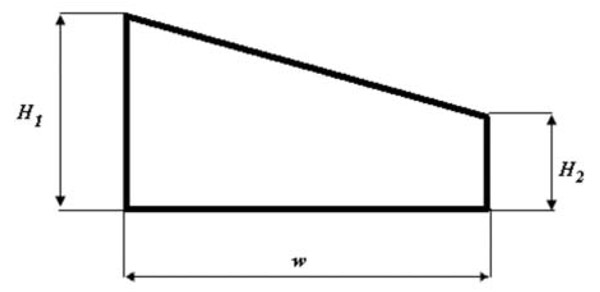 ). This geometry can be used as a simplified model of wing boxes. Their stiffness can be used for aeroelastic applications. It is also important to remark that such stiffness parameters are independent from the angle of sweep of the wing.
 |
Fig. (21) Trapeze cross section: geometrical properties. |
Top and bottom walls are built with laminates having the following volume fractions: 40% 0 degrees fibres, 20% 90 degrees fibres and 40% α degrees fibres, with α varying between 0 and 90 degrees. Vertical walls are orthotropic. They are made by 20% 90 degrees fibres, 40% 0 degrees fibres and 40% 45 degrees fibres. Appropriate elastic properties are those reported in section 3.1.
Geometrical properties are described in Table 2.
The analytical model for EI described in section 1 can be applied once the structural symmetry of the cross section is found, even if the structure in not geometrically symmetric. In other words, the analytical model can be applied once the neutral axis (only for bending along the Y-axis) is found, as shown in Fig. (22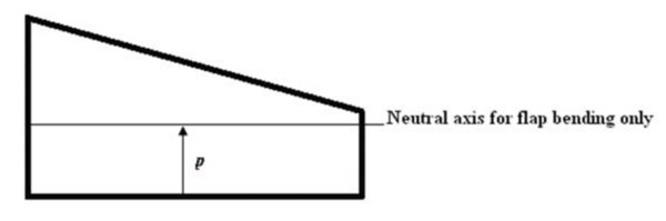 ). The neutral axis is such that
 |
Fig. (22) Neutral axis of a trapeze cross section. |
 |
(24) |
Where:
Zn the distance of the point of the cross section from the neutral axis.
The position of this neutral axis varies slightly with the angle α. However, when the difference between the lengths of left and right walls is not large, and it is often the case of wing box models, the position of the neutral axis with the respect to the axis shown in Fig. 22 can be calculated by using the simplified formula
 |
(25) |
Where:
p the height of the neutral axis (Fig. 21).
H1 the height of the left wall
H1 the height of the right wall
Bending stiffness is calculated by applying the analytical formulation of section 1 to the semi-rectangular cross sections placed below the neutral axis.
Models to evaluate GK and K can be applied to trapeze cross sections without difficulties. Numerical results are shown in Figs. (23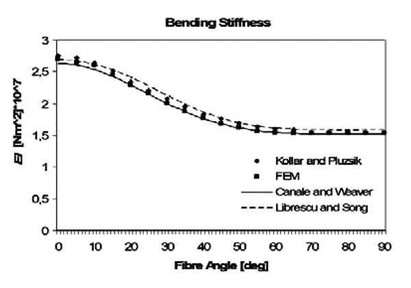 , 24
, 24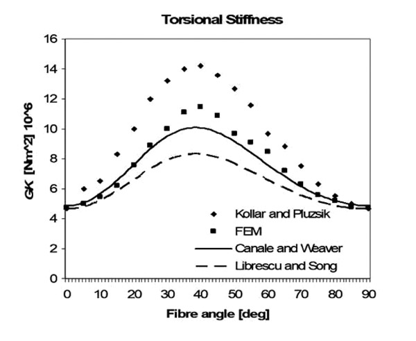 and 25
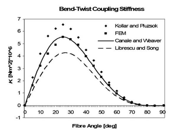 ). The analytical model has been compared, also in this case, with the models of Kollar and Librescu and with FE results, obtained with the same technique described in section 3.1. Concerning EI, all the models produce almost the same result. Regarding K and GK, the analytical model is the only one with a good level of accuracy. It is important to remark that the model of Librescu underestimates the torsional stiffness, even if no parabolic correction is applied. The model of Canale and Weaver, on the other hand, predicts good results because of the assumption resumed in Eq.23.
 |
Fig. (23) Bending stiffness of a trapeze cross section with realistic laminates. |
 |
Fig. (24) Torsional stiffness of a trapeze cross section with realistic laminates. |
 |
Fig. (25) Bend-twist coupling stiffness of a trapeze cross section with realistic laminates. |
4. DISCUSSION
With regards to the bending stiffness EI, the current analytical formulation gives the same level of accuracy as the model of Kollar and Pluzsik but its formulation is simpler. The current model does not evaluate the contribution of vertical and horizontal walls separately. The contribution of the top and bottom walls to EI is considered as a function of the stiffness of the vertical walls and vice versa.
With regards to the torsional stiffness, GK, the current analytical model is able to give accurate results for several geometries (rectangular and trapeze cross sections) and lay-ups (high anisotropy or realistic laminates) while the other models underestimate or overestimate the stiffness. The model of Librescu and Song has been enhanced in two steps. In the first one, a parabolic distribution of the maximum shear flow has been applied. In the second one, the average shear flow has been calculated in order to apply the Bred’s formulation of thin walled closed cross sections.
CONCLUSION
- An analytical model to evaluate bending and torsional stiffness of a composite box has been presented. It is relatively accurate, simple and based on physical reasoning. It can be also easily extended to trapeze cross sections. For cross sections with high level of anisotropy, the accuracy of the proposed formulation is within 2% for EI and within 6% for GK whilst other models can give errors of ca. 40% and 100% respectively. These percentages of error of the proposed model have been approximately found constant for all the geometries analysed. The percentage of error is even further reduced when more realistic (and less anisotropic) laminates are used.
- Analyses performed on EI and GK show that the formulation proposed is able to give highly accurate results for different dimensions, length ratios of horizontal and vertical walls and different lay-ups.
NOMENCLATURE
| Aij | Term of the A matrix of classical lamination theory [Nm-1] |
| EI | The bending stiffness [Nm2] |
| GK | The torsional stiffness [Nm2] |
| 2h | Height of the vertical wall of the box [m] |
| K | The bend-twist coupling stiffness [Nm2] |
| M(X) | The bending moment at the span wise coordinate x [Nm] |
| Nx | Axial force per unit of length [Nm-1] |
| Nxy | Shear force per unit of length [Nm-1] |
| Ny | Lateral force per unit of length [Nm-1] |
| T(X) | The twisting moment at the span wise coordinate x [Nm] |
| th | Thickness of the horizontal wall of the box [m] |
| tv | Thickness of the vertical wall of the box [m] |
| w | Length of the horizontal wall [m] |
| X | The span wise coordinate along the main dimension of the beam [m] |
| εx | The axial strain |
| εy | The lateral strain |
| νxy | Poisson’s number of the laminate |
| γxy | Shear strain |
| ϑ(X) | The twisting angle at the span wise coordinate x [m-1] |
| φ(X) | The flexural angle and the span wise coordinate x [m-1] |
| Ω | Area enclosed by the cross section [m2] |
CONSENT FOR PUBLICATION
Not applicable.
CONFLICT OF INTEREST
The authors declare no conflict of interest, financial or otherwise.
ACKNOWLEDGEMENTS
Declared none.
REFERENCES
| [1] | T.A. Weisshaar, C. Nam, and A. Baptista-Rodriguez, "Aeroelastic Tailoring for Improved UAV Performance", AIAA Paper 98-1757. Presented at the 39th AIAA/ASME/ASCE/AHS/ASC Structures, Structural Dynamics, and Materials Conference American Institute of Aeronautics and Astronautics Long Beach, California, pp. 20-23. [http://dx.doi.org/10.2514/6.1998-1757] |
| [2] | C.E. Cesnik, D.H. Hodges, and M.J. Patil, "Aeroelastic Analysis of Composite Wings", Proceedings of the 37th Structures, Structural Dynamics, and Materials Conference, AIAA paper-96-1444-CP AIAA/ASME/ASCE/AHS/ASC, 1996, pp. 1113-1123 |
| [3] | W. Hequan, C. Libo, and M. Hongfeng, "Crashworthiness Optimization of Thin-Walled Rail with Different Collision Boundary Conditions", Open Mech. Eng. J., vol. 9, pp. 558-563. [http://dx.doi.org/10.2174/1874155X01509010558] |
| [4] | W. Dengfeng, Y. Yongfu, P. Licheng, and D. Haijin, "Study of Load Bearing Capacity of Profiled Steel Sheet Wall Subjected to Combined Bending and Vertical Compression in Electrostatic Precipitator", Open Mech. Eng. J., vol. 8, pp. 326-331. [http://dx.doi.org/10.2174/1874155X01408010326] |
| [5] | T.A. Weisshaar, "Aeroelastic Tailoring-Creative use of unusual materials", 28th proceeding AIAA/ASME/ASCE/AHS/ASC Structural Dynamics and Materials Conference, American Institute of Aeronautics and Astronautics: Monterey, California, . |
| [6] | L.W. Rehfield, A.R. Atilgan, and D.H. Hodges, "Nonclassical behaviour of thin-walled composite beams with closed cross-sections", J. Am. Helicopter Soc., vol. 35, no. 2, pp. 42-50. [http://dx.doi.org/10.4050/JAHS.35.42] |
| [7] | L. Librescu, and O. Song, "On the static aeroelastic tailoring of composite aircraft swept wings modelled as thin-walled beam structures", Compos. Eng., vol. 2, no. 5-7, pp. 497-512. [http://dx.doi.org/10.1016/0961-9526(92)90039-9] |
| [8] | V. Berdichevsky, E. Armanios, and A. Badir, "Theory of anisotropic thin-walled closed cross-section beams", Compos. Eng., vol. 2, no. 5-7, pp. 411-432. [http://dx.doi.org/10.1016/0961-9526(92)90035-5] |
| [9] | C. Kim, and S.R. White, "Thick-walled composite beam theory including 3D elastic effects and torsional warping", J. Solid Struct., vol. 34, no. 31-32, pp. 4237-4259. [http://dx.doi.org/10.1016/S0020-7683(96)00072-8] |
| [10] | L.P. Kollar, and A. Pluzsik, "Analysis of thin-walled composite beams with arbitrary layup", J. Reinf. Plast. Compos., vol. 21, no. 16, pp. 1423-1465. [http://dx.doi.org/10.1177/0731684402021016928] |
| [11] | F. Maceri, and G. Vairo, "Anisotropic thin walled beam models: A rational deduction from three dimensional elasticity", J. Mech. Mater. Struct., vol. 4, no. 2, pp. 371-394. [http://dx.doi.org/10.2140/jomms.2009.4.371] |
| [12] | S.L. Lemanski, and P.M. Weaver, "Flap-torsion coupling in sandwich beams and filled box sections", Thin-walled Struct., vol. 43, no. 6, pp. 923-955. [http://dx.doi.org/10.1016/j.tws.2004.12.004] |
| [13] | M.G. Günay, and T. Timarci, "Static analysis of thin walled laminated composite close sections beams with variable stiffness", Compos. Struct., vol. 192, pp. 67-78. [http://dx.doi.org/10.1016/j.compstruct.2017.08.092] |
| [14] | C. Zhang, and S. Wang, "Structure mechanical modelling of thin walled closed section composite beams, Part 1: Single cell cross section", Compos. Struct., vol. 113, pp. 12-22. [http://dx.doi.org/10.1016/j.compstruct.2014.03.005] |
| [15] | E. Carrera, M. Filippi, P.K. Mahato, and A. Pagani, "Accurate static response of single and multi-cell laminated box beams", Compos. Struct., vol. 136, pp. 372-383. [http://dx.doi.org/10.1016/j.compstruct.2015.10.020] |
| [16] | Z. Gurdal, R.T. Haftka, and P. Hajela, Design and optimization of Laminated composite materials., Wiley Interscience: New York, . |
| [17] | Pitagora Ed. Erasmo Viola, Theory of Constructions, Theory of Elasticity, Vol. 1 , 1990, p. 628. ISBN: 978-8837104931 |
| [18] | MSC software, MSC Nastran 2016. Newport Beach, CA, 2016. Available from: http://documents.mscsoftware.com/ sites/default/files/ro_nastran-2016_ltr_w.pdf |