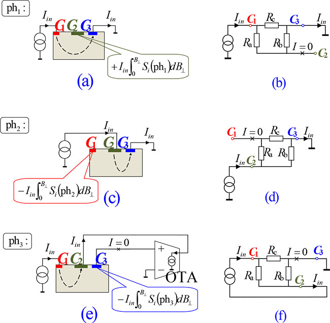
shown in (a, c, e), which have to be added to the potentials at the indicated contacts to account for the Hall effect.
shown in (a, c, e), which have to be added to the potentials at the indicated contacts to account for the Hall effect.
shown in (a, c, e), which have to be added to the potentials at the indicated contacts to account for the Hall effect.