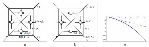
Fig. (7) In (a), schematic picture of the projected stress field corresponding to the stress function (17): here A = a2/(8(h2 − hh1 − hh2 + 2h1h2)), B = b2/(8(h2 − hh1 − hh2 + 2h1h2)), 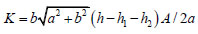 . In (b) schematic picture of the projected stress field corresponding to the stress function (17), in the case study; the load per unit area p must be given in kNm-2, and the projected stress components, are generalized stresses which read in kNm-1. In (c), plot of the projected axial force along the diagonals (dashed line) and of the axial force along the fold (solid line), as a function of x1, in the interval [−a/2, a/2].