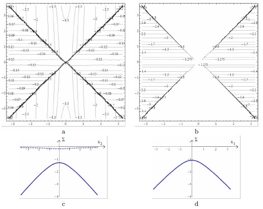
Fig. (8) Contour plot of the physical stress components Σ(11) (a) and Σ(22) (b). In (c), plot of
the physical stresses Σ(11) (dashed line) and Σ(22) (solid line), at x1 = a/2, versus x2. Notice
that the stress Σ(11), at x1 = a/2, represents the thrust per unit length applied horizontally
to the supporting arch/wall. In (d), plot of the physical stress Σ(11), at x2 = b/2, versusx1.
To read the pictures dimensionally, the load per unit area p must be given in kNm-2, and
the projected stress components, are generalized stresses given in kNm-1.