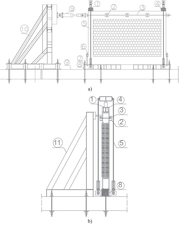
Fig. (5)
Layout of the test setup a) Layout of the in-plane experimental test setup, a) front and b) lateral view.
hydraulic jack (for axial load application), 2 – plates for horizontal force distribution, 3 – horizontal high-strength rods (ø30mm), 4 - head steel shape, 5 – vertical high-strength rods (ø30mm), 6 - steel rod (ø20mm) connecting the RC frame to the foundation steel shape, 7 - high-strength rods (ø30mm) fixing the foundation steel shape to the reaction slab, 8 - foundation steel shape, 9 – strong floor, 10 – in-plane reaction frame 11 – out-of-plane reaction and guiding structure.