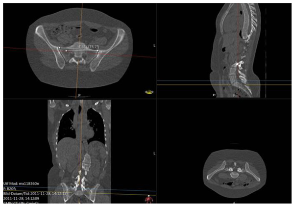
Fig. (4)
See the text describing steps (i)-(iv). The upper left subfigure shows the achieved angle of the sacrum versus the bed, note that it passes through anterosuperiormost part of the sacro-iliac joints, in the given slice. The upper right subfigure shows a plane, which from a sagittal view passes the anterosuperior margin of S1: The blue line in the lower left figure shows the tilting chosen for the sacrum (see main text for more details). The angle representing the tilt and rotation of sacrum (or rather S1) relative to the scanner bed, is the angle between the projection (on an axial plane) of the line in the upper left subfigure (the line depicted between the sacroiliac joints), and the axial horizontal axis.