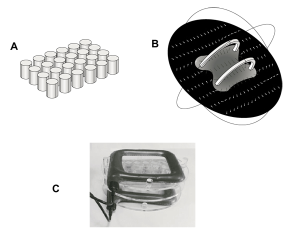
Fig. (1)
Description of ELF MF exposure system. Panel A shows the schematic geometry of multiwells used in a simulation model. Panel B shows a computer modeling of the magnetic field between coils, with arrows indicating magnetic field (H) strength and direction, demonstrating a constant distribution within whole multiwell plate. Panel C shows a picture of the exposure system with the Plexiglass holder keeping multiwell plate between coils.