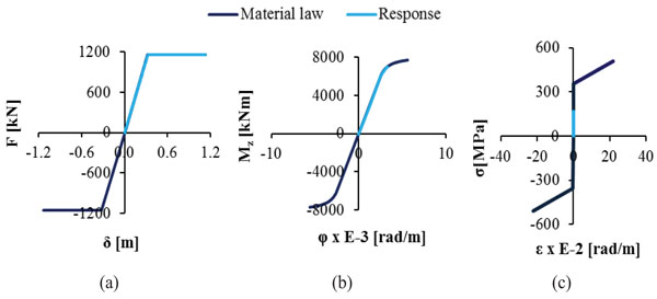
Fig. (14)
Response of the bridge components to ground displacement dy (a) Maximum Force – Displacement (F-δ) diagram for the bearings of the pier, (b) Moment – Curvature (M-φ) diagram for the outer pier column, (c) Maximum stress – strain (σ-ε) diagram for the hangers.