| Step |
In the most stressed section |
Isolated member |
| 1 |
Calculate the design values of the compressive force and bending moment on the member |
NEdMy,Rd
|
| 2 |
Calculate the compression and bending resistances of the cross section according with the cross section class |
Nc,RkMc,Rk
|
| 3 |
Calculate the pure elastic critical compressive force according to minor axis flexural buckling Ncr and the pure elastic critical bending moment of the member Mcr
|
NcrMcr
|
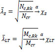
| 4 |
Calculate the member slenderness and reduction factors separately for pure minor axis flexural buckling and pure lateral-torsional buckling (λ, χ, λLT and χLT) |
 |
| 5 |
Calculate the interaction factors connecting the two pure buckling cases (Annex A or Annex B) |
kzy |
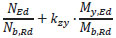
| 6 |
Calculate the design buckling resistance of the member and check the member combination of axial load and bending |
 |