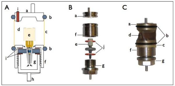
Fig. (1) Schematic illustration of dynamic loading set up (A), photo of the different components prior to assembly (B) and fully assembled
set-up (C). a. Antagonist, b. Tightening O-rings, c. Elastic semi-transparent lever, d. Upper compartment holding the indication medium, e. A
mounted implant sample, f. Capping holder of lower chamber, g. Lower chamber compartment with screw third for tightening, h. Mounting
holder for chewing machine cell, i. Indicating medium filling inlet, j. Sealing rubber washers.