- Home
- About Journals
-
Information for Authors/ReviewersEditorial Policies
Publication Fee
Publication Cycle - Process Flowchart
Online Manuscript Submission and Tracking System
Publishing Ethics and Rectitude
Authorship
Author Benefits
Reviewer Guidelines
Guest Editor Guidelines
Peer Review Workflow
Quick Track Option
Copyediting Services
Bentham Open Membership
Bentham Open Advisory Board
Archiving Policies
Fabricating and Stating False Information
Post Publication Discussions and Corrections
Editorial Management
Advertise With Us
Funding Agencies
Rate List
Kudos
General FAQs
Special Fee Waivers and Discounts
- Contact
- Help
- About Us
- Search


The Open Electrical & Electronic Engineering Journal
(Discontinued)
ISSN: 1874-1290 ― Volume 13, 2019
Creating a Gain Improvement Technique for a Horn Antenna using a Metamaterial Structure Inserted with a Thin Dielectric Sheet
Paowphattra Kamphikul1, *, Ukrit Mankong1, Rangsan Wongsan2
Abstract
Objective:
This paper proposed a new technique for the metamaterial on the structure of the curved-woodpile Electromagnetic Band Gap (EBG) inserted with a dielectric slab for gain improvement in a conventional rectangular horn antenna.
Methods:
We described a method to enhance gain by transferring the electromagnetic fields from the aperture of a horn through the EBG structure. Furthermore, we present the design procedures for inserting a dielectric slab into two layers of the EBG structure for the reduction of distance between the horn and proposed EBG structure.
Results and Conclusions:
Such a proposed technique not only has the advantage of decreasing the total length of the antenna system but also providing higher gain with a low profile structure.
This idea has been verified by both simulation and experimental results. The fabricated antenna can achieve 23.9 dBi of gain or higher than the gain, which is obtained using a conventional rectangular horn antenna at around 7 dBi at an operating frequency of 10 GHz. It is apparent that a good qualitative agreement between the measurements and simulations was achieved.
Article Information

Identifiers and Pagination:
Year: 2019Volume: 13
First Page: 30
Last Page: 40
Publisher Id: TOEEJ-13-30
DOI: 10.2174/1874129001913010030
Article History:
Received Date: 31/10/2018Revision Received Date: 08/04/2019
Acceptance Date: 17/04/2019
Electronic publication date: 31/05/2019
Collection year: 2019
open-access license: This is an open access article distributed under the terms of the Creative Commons Attribution 4.0 International Public License (CC-BY 4.0), a copy of which is available at: https://creativecommons.org/licenses/by/4.0/legalcode. This license permits unrestricted use, distribution, and reproduction in any medium, provided the original author and source are credited.
* Address correspondence to this author at the Department of Electrical Engineering, Chiang Mai University, Chiang Mai 50200, Thailand at;
Tel: +6653944140; Fax: +6653944140; E-mail: paowphattra.k@cmu.ac.th
| Open Peer Review Details | |||
|---|---|---|---|
| Manuscript submitted on 31-10-2018 |
Original Manuscript | Creating a Gain Improvement Technique for a Horn Antenna using a Metamaterial Structure Inserted with a Thin Dielectric Sheet | |
1. INTRODUCTION
At present, a horn is extensively used as an antenna at ultra-high frequency (UHF) and microwave frequencies above 300 MHz [1A.B. Constantine, Antenna Theory: Analysis and Design., John Wiley & Sons, Inc.: New Jersey, .]. It is an aperture antenna type that has a moderately high gain compared to other antennas. For this reason, it is widely applied in various tasks such as satellite communications, radio astronomy, and radar or remote sensing [2A.W. Love, Electromagnetic horn antennas., IEEE Press: New York, .-3A.D. Olver, P.J.B. Clarricoats, L. Shafai, and A.A. Kishk, Microwave horns and feeds., IEEE Press: New York, .
[http://dx.doi.org/10.1049/PBEW039E] ]. It is used as a feeder for larger antenna structures, especially the parabolic reflector antenna, as a standard calibrated antenna to measure the gain of other antennas, and as a directive antenna [4U.A. Bakshi, and A.V. Bakshi, Antennas and Wave Propagation., Technical Publications, .-5V. Rodriguez, A brief history of horns, Compliance Magazine, .].
Although the important advantage of the horn antenna is that it provides high directivity and gain, the horn antenna should have a large aperture for larger gains. To achieve the maximum gain for given aperture size, the taper should be long so that the phase of the wavefront is as nearly constant as possible across the aperture. Moreover, the length of the horn also becomes excessive when the horn opening is made larger. As a result, gain levels of the horn antenna are a balance between aperture size and length, usually limited to 20 dB. From this study, the gains of a basic horn and the proposed horn antennas can achieve around 17 dBi and 24 dBi, respectively. We found that the gain of a horn at 24 dB should have an aperture area of 0.035 m2 or larger compared to the area of the aperture. The aperture has been designed with a basic horn antenna around a quintuple. However, this paper proposes a technique for the metamaterial to influence the gain improvement of a conventional rectangular horn antenna without construction enlargement.
Many stimulating new technologies have attracted attention, particularly in modern antenna designs. One exciting breakthrough is the development of metamaterial, which has acceptable electromagnetic properties that cannot be seen in natural materials. All natural materials have positive electrical permittivity, magnetic permeability and an index of refraction. All these metamaterial parameters are near zero, zero, and negative, respectively [6R.S. Kshetrimayum, "A brief intro to metamaterials", IEEE Potentials, vol. 23, no. 5, pp. 44-46.
[http://dx.doi.org/10.1109/MP.2005.1368916] ]. In addition, the application of metamaterial for Electromagnetic Band Gap (EBG) structure in antenna designs has attracted increasing interest for antenna engineering [7F. Yang, and Y. Rahmat-Samii, Electromagnetic Band Gap Structures in Antenna Engineering., Cambridge University Press: Cambridge, .]. The EBG structure is able to eliminate the drawbacks of conducting ground-planes, to preclude the surface wave propagation, lower the device profiles, and improve the performance of antennas by enhancing their directivity and radiation efficiency [8R. Gonzalo, P. de Maagt, and M. Sorolla, "Enhanced Path-Antenna Performance by Suppressing Surface Waves using Photonic-Bandgap Substrates", IEEE Trans. Microw. Theory Tech., vol. 47, no. 11, pp. 2131-2138.
[http://dx.doi.org/10.1109/22.798009] , 9M. Thevenot, C. Cheype, A. Reineix, and B. Jecko, "Directive Photonic Band-Gap Antennas", IEEE Trans. Microw. Theory Tech., vol. 47, no. 11, pp. 2115-2122.
[http://dx.doi.org/10.1109/22.798007] ]. The electromagnetic properties of an EBG structure are determined by its physical dimensions, which are the important parameters to design and optimize them. For 2D EBG structures such as the mushroom-like EBG, there are four main parameters affecting performance [10F. Yang, and Y. Rahmat-Samii, "Reflection phase characterizations of the EBG ground plane for low profile wire antenna applications", IEEE Trans. Antenn. Propag., vol. 51, no. 10, pp. 2691-2703.
[http://dx.doi.org/10.1109/TAP.2003.817559] ], namely patch width, gap width, substrate thickness, and substrate permittivity. Meanwhile, the defect resonant frequency is a function of the cavity size for 3D EBG structures such as woodpile EBG [11A.R. Weily, L. Horvath, K.P. Esselle, B. Sanders, and T. Bird, "A planar resonator antenna based on woodpile EBG material", IEEE Trans. Antenn. Propag., vol. 53, no. 1, pp. 216-223.
[http://dx.doi.org/10.1109/TAP.2004.840531] ].
In the current study, we found that the proper structure of a resonant EBG installed in the front of the horn aperture is able to increase the horn’s gain. From the literature review, planar- and cylindrical-woodpile EBG structures [11A.R. Weily, L. Horvath, K.P. Esselle, B. Sanders, and T. Bird, "A planar resonator antenna based on woodpile EBG material", IEEE Trans. Antenn. Propag., vol. 53, no. 1, pp. 216-223.
[http://dx.doi.org/10.1109/TAP.2004.840531] , 12Y. Lee, X. Lu, Y. Hao, S. Yang, J.R.G. Evans, and C.G. Parini, "Narrow-beam azimuthally omni-directional millimetre-wave antenna using freeformed cylindrical woodpile cavity", IET Microw. Antennas Propag., vol. 4, no. 10, pp. 1491-1499.
[http://dx.doi.org/10.1049/iet-map.2009.0224] ] are more suitable for beam shape, which has been obtained by a rectangular horn antenna. Consequently, this paper considers the advantages of the EBG structure in proposing and studying the technique to improve the gain of a conventional rectangular horn antenna by using a curved-woodpile EBG structure inserted with a dielectric slab between two layers of the curved-woodpile EBG to reduce the distance between a horn and EBG structure. We simulate and fabricate a horn antenna with curved-woodpile EBG structure based on low-loss aluminum rods at a dominant frequency of 10 GHz. The proposed structure provides the ability to control and manipulate the flow of electromagnetic waves. Also, the proposed antenna not only has a high gain but also low profile and lightweight, extending the scope of its utilization for X-band (8 – 12 GHz) and I-band (8 – 10 GHz) beyond the IEEE and the ITU standards, respectively.
This paper is organized as follows: Section 2 summarizes the configurations and design of the basic horn antenna and the curved-woodpile EBG structure with corresponding band gap features at 10 GHz of the operating frequency. Next, we simulate the antenna design by using simulation software and presenting discussions of the design parameters in Section 3. Section 4 provides the measurement results of the fabricated prototype antenna with illustrations and discussion. Finally, the conclusions are given.
2. HORN ANTENNA AND EBG CONFIGURATIONS
2.1. A Conventional Rectangular Horn Antenna Configuration
A horn antenna is composed of a flaring metal waveguide to conduct the electromagnetic waves into free space. The important dimensions of a horn antenna are horn length, aperture area, and flare angle. The design of a conventional rectangular horn antenna is initiated by determining its aperture dimension [1A.B. Constantine, Antenna Theory: Analysis and Design., John Wiley & Sons, Inc.: New Jersey, .], as shown in Fig. (1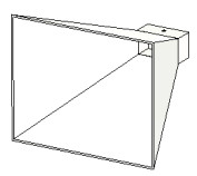 ). In order to obtain the referenced gain of this rectangular horn antenna before being added to the proposed EBG structure, the dimensions of horn are given and simulated to find its directive gain, BandWidth (BW), SideLobe Level (SLL), and Half Power Beam Width (HPBW) in both planes, shown as the ratio of Azimuth Pattern to Evaluation Pattern (AZ:EL) and displayed in the first row of Table 1.
 |
Fig. (1) Configuration of a conventional rectangular horn antenna. |
2.2. The Curved-Woodpile EBG Configuration
From this study, it was found that a proper EBG structure is able to improve the gain of a basic horn antenna when an additional resonant circuit is installed in the front of the horn. This is because we can control and manipulate the flow of electromagnetic waves as required. Moreover, there is a frequency range in the EBG structure that propagates modes that can be fully suppressed in one or more dimensions. This range of frequency can provide the suppression and conduction of radiation performance when operated with antennas. It can be properly shaped, such as planar woodpile for reducing the side and the back lobes of the directional antenna as mentioned in the study [13Y. Lee, X. Lu, Y. Hao, S. Yang, J.R.G. Evans, and C.G. Parini, "Low profile directive millimeter-wave antennas using free formed three-dimensional (3D) electromagnetic band gap structures", IEEE Trans. Antenn. Propag., vol. 57, no. 10, pp. 2893-2903.
[http://dx.doi.org/10.1109/TAP.2009.2029299] ]. A similar geometry as the planar woodpile is also used for the design of a cylindrical woodpile, which is different from the planar woodpile in that the horizontal filaments are not inserted in the cylindrical woodpile but rather aligned at the same horizontal location. Therefore, the Transverse Magnetic (TM) resonant mode will occur in the cylindrical cavity because the structure does not demand the three-dimensional bandgap, just require the bandgap along the radial direction. Since the cylindrical cavity requires excitation with vertical (axis of the cylinder) electric fields, vertically aligned gratings are necessary, which are achieved by stacked horizontal filaments crossing at the same location. However, we found from the investigation that the sector of curved-woodpile EBG structure is more suitable for the beam shape of a conventional rectangular horn antenna. Due to the decrease of side and back lobes of the radiation pattern of a horn antenna achieved by the planar woodpile, the curved cylindrical woodpile can produce the phases of wave transmission from a horn antenna equally, resulting in ultimate resonance. Therefore, this paper applies the similar geometry of the planar and cylindrical woodpiles to design a sector of curved-woodpile EBG structure for the first time. Fig. (2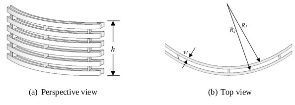 ) shows the geometry of the curved-woodpile EBG structure with two layers of different diameters. The important parameters of the structure are the filament thickness or diameter (w), the inner (R1) and outer (R2) radii, the height (h), the number of radial filaments (Nrad), and the number of the ring sector (Nring). To implement the curved-woodpile EBG, we used aluminum rods (rectangular cross-section) with parameters εr = 8.4 and tanδ = 0.002. From the literature review [14P. Kamphikul, and R. Wongsan, "Gain Improvement for Rectangular Horn Antenna by Using Curved-Woodpile Metamaterial", Proc. Conference of the 2016 13th IEEE International Conference on Electrical Engineering/Electronics, Computer, Telecommunications and Information Technology, pp. 1-4.
[http://dx.doi.org/10.1109/ECTICon.2016.7561349] , 15R. Wongsan, and P. Kamphikul, "A Triangle Array of 1x4 Slots Antenna with Curved EBG Structures for Cellular Base Station", Progress In Electromagnetics Research C, vol. 70, pp. 155-164.
[http://dx.doi.org/10.2528/PIERC16091601] ], we found that the variation of R had an effect on the HPBW in the H-plane, while HPBW will be enlarged when the dimension of R is increased. Moreover, the gain of the horn antenna is increased when h is also increased. However, the operating frequency of bandwidth will be shifted to an undesirable frequency if h is higher than 2.1λ (6 layers). Therefore, the parameters are designed and optimized for the most appropriate efficiency as follows: w = 0.08λ, R1 = 14.4λ, R2 = 14.7λ, h = 2.1λ, Nrad = 3, and Nring = 2 [14P. Kamphikul, and R. Wongsan, "Gain Improvement for Rectangular Horn Antenna by Using Curved-Woodpile Metamaterial", Proc. Conference of the 2016 13th IEEE International Conference on Electrical Engineering/Electronics, Computer, Telecommunications and Information Technology, pp. 1-4.
[http://dx.doi.org/10.1109/ECTICon.2016.7561349] , 15R. Wongsan, and P. Kamphikul, "A Triangle Array of 1x4 Slots Antenna with Curved EBG Structures for Cellular Base Station", Progress In Electromagnetics Research C, vol. 70, pp. 155-164.
[http://dx.doi.org/10.2528/PIERC16091601] ].
In order to analyze the unique features of the curved-woodpile EBG inserted with a thin dielectric sheet, the lumped element model of the resonant circuit is implemented, as shown in Fig. (3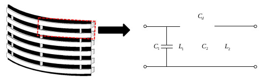 ). From the simulated results using the given parameters to design and optimize the most appropriate efficiency in accordance with the study [14P. Kamphikul, and R. Wongsan, "Gain Improvement for Rectangular Horn Antenna by Using Curved-Woodpile Metamaterial", Proc. Conference of the 2016 13th IEEE International Conference on Electrical Engineering/Electronics, Computer, Telecommunications and Information Technology, pp. 1-4.
[http://dx.doi.org/10.1109/ECTICon.2016.7561349] -15R. Wongsan, and P. Kamphikul, "A Triangle Array of 1x4 Slots Antenna with Curved EBG Structures for Cellular Base Station", Progress In Electromagnetics Research C, vol. 70, pp. 155-164.
[http://dx.doi.org/10.2528/PIERC16091601] ], it was found that capacitance C or the radius (R) of the curved-woodpile EBG structure can be used to adjust the HPBW, while inductance L or the height (h) of the curved-woodpile EBG structure can be used to control the resonant frequency and the bandwidth of the antenna. As depicted in Fig. (4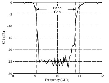 ), the frequency range with transmission coefficient (S21) of less than −10 dB, usually considered the band gap, is achieved over the frequency bandwidth from 9.22 GHz to 10.72 GHz. Over this bandwidth, propagation is prohibited by the EBG or no surface wave propagation. Regarding the EBG design for antenna applications, the transmission responses are utilized to investigate the bandgap characteristics, especially the surface wave bandgap of the EBG structure, which can be easily identified.
 |
Fig. (2) The geometry for the sector of curved-woodpile EBG structure. |
 |
Fig. (3) The resonant circuit. |
 |
Fig. (4) Simulated transmission coefficient of the proposed EBG structure. |
3. SIMULATED RESULTS AND DISCUSSIONS
The simulated results of a conventional rectangular horn antenna with the sector of curved-woodpile EBG structure that is vertically placed in front of a horn with the optimized distance between a horn and the curved-woodpile EBG d = 16λ [14P. Kamphikul, and R. Wongsan, "Gain Improvement for Rectangular Horn Antenna by Using Curved-Woodpile Metamaterial", Proc. Conference of the 2016 13th IEEE International Conference on Electrical Engineering/Electronics, Computer, Telecommunications and Information Technology, pp. 1-4.
[http://dx.doi.org/10.1109/ECTICon.2016.7561349] ] are shown in Fig. (5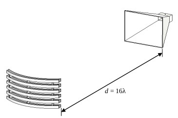 ). We found that the proper structure of the curved-woodpile is capable of increasing the gain by around 7 dBi adding only one appropriate EBG structure. Moreover, comparisons of the S11, the Voltage Standing Wave Ratio (VSWR), and radiation patterns of the single horn with and without curved-woodpile EBG are shown in Figs. (6
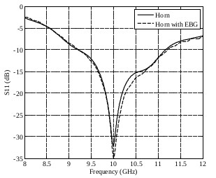 and 8
and 8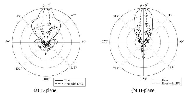 ), respectively. In addition, it is notable that S11 is not affected when the curved-woodpile EBG is installed. The radiation pattern of a horn with curved-woodpile EBG has a low side lobe level and its main beams are symmetrical in both the E-plane and H-plane, as shown in Fig. (7
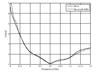 ). Therefore, our proposed curved-woodpile EBG is able to improve the performance of a single horn antenna as observed from its directive gain and enhanced radiation efficiency.
The optimized distance (at d = 16λ) between the horn and curved-woodpile EBG antenna system is still too long, causing installation and utilization to be rather difficult. Therefore, a thin dielectric sheet is proposed by inserting into two layers of the curved-woodpile EBG structure to decrease the distance between the horn and EBG, as shown in Fig. (9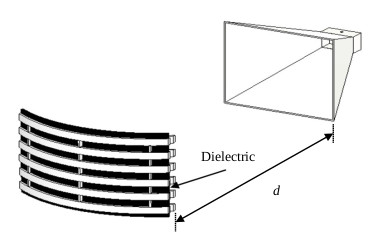 ). In order to realize such a method, the thin sheets of polyamide, silicone, and Teflon, which can be bent easily, are considered by comparing the responses of antenna gain against the shortest distance (d) between a horn and EBG structure. After the simulation, it was found that the highest gain of 24.17 dBi was achieved when the inserted thin dielectric sheet comprised polyamide at d = 10λ, while silicone and Teflon provide the highest gain of 24.07 dBi at d = 10λ and 24.1 dBi at d = 12λ, respectively, as shown in Fig. (10
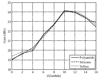 ). Comparisons of the simulated S11, VSWR, and radiation patterns of three different dielectrics are illustrated in Figs. (11
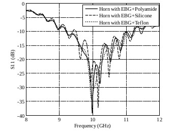 -13
-13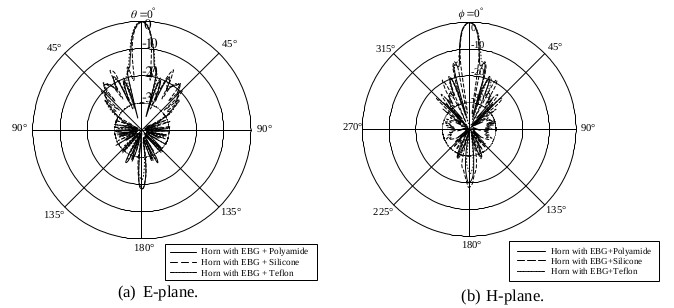 ), respectively. We found S11 ripples when each type of dielectric was inserted into the EBG structure, whereas its bandwidth was not affected. In addition, Table 1 shows a comparison of gains, SLLs, and HPBWs for the horn antennas in three categories. We note that, after inserting the polyamide thin sheet into two layers of the curved-woodpile EBG, it not only reduces the distance between the horn and EBG, but also improves the gain of the antenna. Therefore, polyamide is used as the dielectric material in the current work and placed at a distance of d = 10λ.
 |
Fig. (5) A horn with curved-woodpile EBG at d = 16λ. |
 |
Fig. (6) Simulated results of the S11 for a horn and a horn with EBG. |
 |
Fig. (7) Simulated results of the VSWR for a horn and a horn with EBG. |
 |
Fig. (8) Simulated results of the radiation patterns for a horn and a horn with EBG. |
 |
Fig. (9) A horn with curved-woodpile EBG and a dielectric sheet inserted between its layers. |
 |
Fig. (10) Simulated results of gain against d for horns with EBG structure inserted in each type of dielectric. |
 |
Fig. (11) Simulated results of S11 for horns with EBG structure inserted in each type of dielectric. |
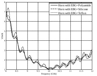 |
Fig. (12) Simulated results of VSWR horns with EBG structure inserted in each type of dielectric. |
 |
Fig. (13) Simulated results of radiation patterns of horns with EBG structure inserted in each type of dielectric. |
4. EXPERIMENTAL RESULTS AND DISCUSSION
In order to verify the proposed antenna and EBG structure, the measured results for horn antenna and curved-woodpile EBG prototype are presented in this section. The horn antenna and proposed EBG structure are fabricated for an operating frequency of 10 GHz, as shown in Fig. (14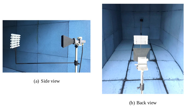 ). Subsequently, its performance is tested and measured for validation of the proposed concept. The prototype antenna for measurement setup consists of a rectangular horn and the two-layer curved-woodpile EBG inserted with a thin polyimide sheet (3 mm of thickness) between its layers, which exhibits bandgap characteristics at the desired bandwidth and 10 GHz of the center frequency. The simulated and measured S11 and VSWR for this antenna are shown in Figs. (15
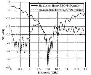 and 16
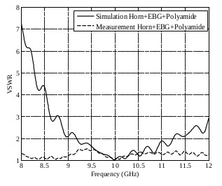 ), respectively. It is observed that the simulated and measured results are in good agreement at a resonant frequency from 9.5 GHz to 10.5 GHz. Even though the S11 of the measured result provides more ripple than the simulated result, it is capable of retaining the desired frequency band gap, as previously specified. However, the proposed antenna with EBG structure has focused on radiation performance, especially directive gain and SLL. The simulated and measured patterns are compared, as shown in Fig. (17
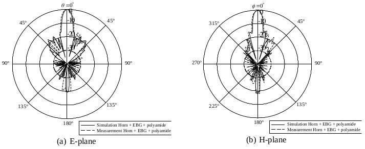 ). It is observed that there is good agreement between the predictions and measured data. The measured gain of the proposed antenna is 23.9 dBi at an operating frequency of 10 GHz when d = 10λ, as shown in Fig. (18
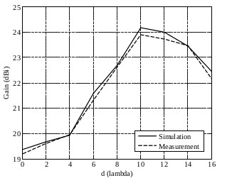 ).
).
The measured S11, VSWR, and radiation pattern of a conventional horn, a horn with curved-woodpile EBG (d = 16λ), and a horn with curved-woodpile EBG and polyamide (d = 10λ) are shown in Figs. (19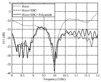 -21
-21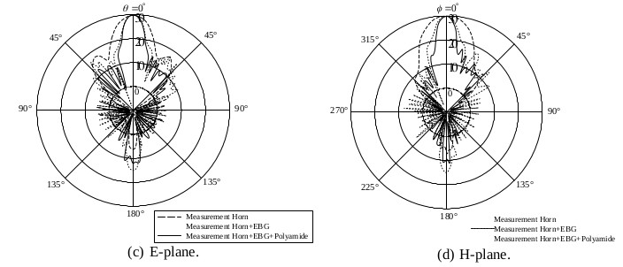 ), respectively. From the measured S11 and VSWR, it can be observed that the EBG structure provides more ripple of S11 and VSWR when compared to a conventional horn. This is due to retaining the desired frequency band gap of the EBG structure, while the polyamide has no effect. Moreover, the radiation pattern results conform to the S11 and VSWR results. The radiation pattern of a horn with a curved-woodpile EBG is similar to the radiation pattern of a horn with curved-woodpile EBG and polyamide. It is noticeable the SLLs and the HPBWs are alike. To investigate the measured gains, we found that a horn with a curved-woodpile EBG and a horn with a curved-woodpile EBG and polyamide yielding a gain at an operating frequency of 10 GHz are higher than the gain for a basic horn at around 7 dBi. However, a horn with a curved-woodpile EBG and polyamide has a shorter distance between the horn and EBG structure. Thus, the technique for the EBG structure in order to improve the gain of a basic horn antenna can be carried out without construction enlargement. Inserting a polyamide slab into two layers of the EBG structure can reduce the distance between the horn and proposed EBG structure. The measured and simulated results for the three categories in terms of gains, bandwidths, and the SLLs, as well as the HPBWs, are summarized in Table 2.
 |
Fig. (14) The measurement setup for horn antenna prototype with proposed EBG structure. |
 |
Fig. (15) The simulated and measured S11 of a horn antenna and proposed EBG structure. |
 |
Fig. (16) The simulated and measured VSWR of a horn antenna and proposed EBG structure. |
 |
Fig. (17) The radiation patterns of the horn antenna with proposed EBG structure. |
 |
Fig. (18) The measured and simulated results of gains against d. |
 |
Fig. (19) Measured results of S11 for horns with EBG structure inserted in each type of dielectric. |
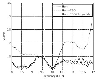 |
Fig. (20) Measured results of VSWR for horns with EBG structure inserted in each type of dielectric. |
 |
Fig. (21) Measured results of the radiation patterns for horns with EBG structure inserted in each type of dielectric. |
CONCLUSION
We presented the creation of gain enhancement with a conventional rectangular horn antenna using a new technique of curved-woodpile EBG structure inserted with a thin dielectric (polyamide) sheet. These results demonstrated that the horn antenna and proposed EBG structure (without inserted dielectric sheet) could increase the directive gain by around 7 dBi when compared to the results obtained from a single horn. The curved-woodpile EBG functions as an additional resonant circuit capable of improving the gain of the original horn antenna. Furthermore, we inserted a thin polyamide sheet between the two layers of the EBG structure. Evidently, it is possible to decrease the distance between the horn and curved-woodpile EBG from 16λ to 10λ, in which the highest gain of 23.9 dBi is obtained. Finally, the simulated and experimental results are in good agreement and according to the requirements of gain improvement for a horn antenna, which will certainly be appropriate for the application of X-band and I-band beyond following the IEEE and ITU standards, respectively.
LIST OF ABBREVIATIONS
| AZ | = Azimuth Pattern |
| BW | = Bandwidth |
| EBG | = Electromagnetic Band Gap |
| EL | = Evaluation Pattern |
| HPBW | = Half Power Beam Width |
| SLL | = Side Lobe Level |
| VSWR | = Voltage Standing Wave Ratio |
CONSENT FOR PUBLICATION
Not applicable.
AVAILABILITY OF DATA AND MATERIALS
Not applicable.
FUNDING
This work was funded by CMU Junior Research Fellowship Program.
CONFLICT OF INTEREST
The authors declare no conflicts of interest, financial or otherwise.
ACKNOWLEDGEMENTS
The authors acknowlege the support from CMU Junior Research Fellowship Program.
REFERENCES
| [1] | A.B. Constantine, Antenna Theory: Analysis and Design., John Wiley & Sons, Inc.: New Jersey, . |
| [2] | A.W. Love, Electromagnetic horn antennas., IEEE Press: New York, . |
| [3] | A.D. Olver, P.J.B. Clarricoats, L. Shafai, and A.A. Kishk, Microwave horns and feeds., IEEE Press: New York, . [http://dx.doi.org/10.1049/PBEW039E] |
| [4] | U.A. Bakshi, and A.V. Bakshi, Antennas and Wave Propagation., Technical Publications, . |
| [5] | V. Rodriguez, A brief history of horns, Compliance Magazine, . |
| [6] | R.S. Kshetrimayum, "A brief intro to metamaterials", IEEE Potentials, vol. 23, no. 5, pp. 44-46. [http://dx.doi.org/10.1109/MP.2005.1368916] |
| [7] | F. Yang, and Y. Rahmat-Samii, Electromagnetic Band Gap Structures in Antenna Engineering., Cambridge University Press: Cambridge, . |
| [8] | R. Gonzalo, P. de Maagt, and M. Sorolla, "Enhanced Path-Antenna Performance by Suppressing Surface Waves using Photonic-Bandgap Substrates", IEEE Trans. Microw. Theory Tech., vol. 47, no. 11, pp. 2131-2138. [http://dx.doi.org/10.1109/22.798009] |
| [9] | M. Thevenot, C. Cheype, A. Reineix, and B. Jecko, "Directive Photonic Band-Gap Antennas", IEEE Trans. Microw. Theory Tech., vol. 47, no. 11, pp. 2115-2122. [http://dx.doi.org/10.1109/22.798007] |
| [10] | F. Yang, and Y. Rahmat-Samii, "Reflection phase characterizations of the EBG ground plane for low profile wire antenna applications", IEEE Trans. Antenn. Propag., vol. 51, no. 10, pp. 2691-2703. [http://dx.doi.org/10.1109/TAP.2003.817559] |
| [11] | A.R. Weily, L. Horvath, K.P. Esselle, B. Sanders, and T. Bird, "A planar resonator antenna based on woodpile EBG material", IEEE Trans. Antenn. Propag., vol. 53, no. 1, pp. 216-223. [http://dx.doi.org/10.1109/TAP.2004.840531] |
| [12] | Y. Lee, X. Lu, Y. Hao, S. Yang, J.R.G. Evans, and C.G. Parini, "Narrow-beam azimuthally omni-directional millimetre-wave antenna using freeformed cylindrical woodpile cavity", IET Microw. Antennas Propag., vol. 4, no. 10, pp. 1491-1499. [http://dx.doi.org/10.1049/iet-map.2009.0224] |
| [13] | Y. Lee, X. Lu, Y. Hao, S. Yang, J.R.G. Evans, and C.G. Parini, "Low profile directive millimeter-wave antennas using free formed three-dimensional (3D) electromagnetic band gap structures", IEEE Trans. Antenn. Propag., vol. 57, no. 10, pp. 2893-2903. [http://dx.doi.org/10.1109/TAP.2009.2029299] |
| [14] | P. Kamphikul, and R. Wongsan, "Gain Improvement for Rectangular Horn Antenna by Using Curved-Woodpile Metamaterial", Proc. Conference of the 2016 13th IEEE International Conference on Electrical Engineering/Electronics, Computer, Telecommunications and Information Technology, pp. 1-4. [http://dx.doi.org/10.1109/ECTICon.2016.7561349] |
| [15] | R. Wongsan, and P. Kamphikul, "A Triangle Array of 1x4 Slots Antenna with Curved EBG Structures for Cellular Base Station", Progress In Electromagnetics Research C, vol. 70, pp. 155-164. [http://dx.doi.org/10.2528/PIERC16091601] |