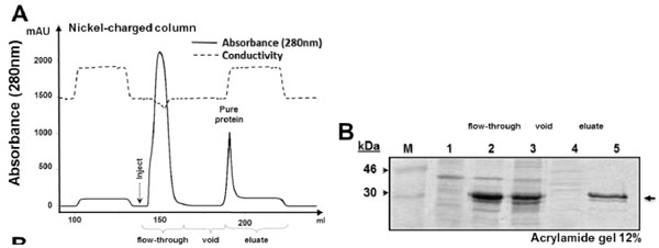
Fig. (2) Expression and purification of His−sfGFP−mutacin fusion protein(A) Diagram of purification procedure using nickel−charged column (5 ml). Continuous line represented the absorbance of the eluate, different purification steps are shown below and peaks of the flow−through sample and of purified sfGFP−mutacin are indicated. Dashed line represented conductivity of the eluate. (B) SDS−PAGE (acrylamide 12 %) of protein samples from the different steps of expression and purification; total cytoplasmic extract before IPTG induction (lane 1), after 16 h of induction (lane 2), after sonication (lane 3), flow−through sample from nickel−charged column (lane 4) and purified sfGFP−mutacin fusion protein (lane 5). Protein molecular weight marker (in kDa) was loaded in the first lane (M), and side arrow referred to the expected location of the recombinant protein in the gel.