- Home
- About Journals
-
Information for Authors/ReviewersEditorial Policies
Publication Fee
Publication Cycle - Process Flowchart
Online Manuscript Submission and Tracking System
Publishing Ethics and Rectitude
Authorship
Author Benefits
Reviewer Guidelines
Guest Editor Guidelines
Peer Review Workflow
Quick Track Option
Copyediting Services
Bentham Open Membership
Bentham Open Advisory Board
Archiving Policies
Fabricating and Stating False Information
Post Publication Discussions and Corrections
Editorial Management
Advertise With Us
Funding Agencies
Rate List
Kudos
General FAQs
Special Fee Waivers and Discounts
- Contact
- Help
- About Us
- Search


The Open Electrical & Electronic Engineering Journal
(Discontinued)
ISSN: 1874-1290 ― Volume 13, 2019
Effect of Errors in Beamforming Analysis Applied for MVDR and CBF Method
Xueping Li1, 2, *, Youcheng Wang3, Zhaoying Wang1, Shu Xu1, Yu Zhang1, 2
Abstract
Minimum Variance Distortionless Response (MVDR) method can achieve a lower null level of beamforming compared to the Conventional Beamformer (CBF) method. It can not only minimize the array system mean output power but also maintain a distortion less response to desired signal as it adaptively depends on sample data. The effect of errors in beamforming analysis is applied using MVDR and CBF method. The errors include variance of weight and steering vector with different input SIR. These errors can affect the performance of array system’s mean output power and SINR for both CBF and MVDR. However, the MVDR method has more robust characteristics compared to the CBF method in the case of slight errors. The errors analysis also shows that factors of variance can weaken the performance of MVDR beamformer for suppressing clutters.
Article Information

Identifiers and Pagination:
Year: 2016Volume: 10
First Page: 197
Last Page: 204
Publisher Id: TOEEJ-10-197
DOI: 10.2174/1874129001610010197
Article History:
Received Date: 19/02/2016Revision Received Date: 11/08/2016
Acceptance Date: 01/09/2016
Electronic publication date: 30/12/2016
Collection year: 2016
open-access license: This is an open access article licensed under the terms of the Creative Commons Attribution-Non-Commercial 4.0 International Public License (CC BY-NC 4.0) (https://creativecommons.org/licenses/by-nc/4.0/legalcode), which permits unrestricted, non-commercial use, distribution and reproduction in any medium, provided the work is properly cited.
* Address correspondence to this author at the College of Electronic and Electrical Engineering, Henen Normal University 46# East of Construction Road, Xinxiang, Henan, China; Tel: +863733326151; Fax: +863733326151; E-mail: lxpslxhhw@126.com
| Open Peer Review Details | |||
|---|---|---|---|
| Manuscript submitted on 19-02-2016 |
Original Manuscript | Effect of Errors in Beamforming Analysis Applied for MVDR and CBF Method | |
1. INTRODUCTION
Array beamforming has been widely applied in radar, sonar, acoustics, communications and various media sound imagings. Minimum Variance Distortionless Response (MVDR) method has a characteristic of adaptive beamforming which depends on the array sample data. MVDR beamformer is known as the modified Capon beamformer for his original work [1J. Capon, "High-resolution frequency-wave number spectrum analysis", Proc. IEEE, vol. 57, no. 8, pp. 1408-1418, 1969.
[http://dx.doi.org/10.1109/PROC.1969.7278] ], and then a variety of beamforming methods have been researched for decreasing the clutters or noise [2S.A. Kassam, and H.V. Poor, "Robust techniques for signal processing: A survey", Proc. IEEE, vol. 73, no. 3, pp. 433-481, 1985.
[http://dx.doi.org/10.1109/PROC.1985.13167] -9G. Liang, K. Liu, and W. Lin, "A new beam-forming algorithm based on flank acoustic vector-sensor array sonar", In: International Conference on Wireless Communications & Signal Processing, Nanjing, China, 2009, pp. 1-5.
[http://dx.doi.org/10.1109/WCSP.2009.5371393] ]. As compared to regular beamformer method, such as Conventional Beamformer (CBF) method, MVDR method can get smaller array mean output power and lower null level of interference degree with the prescribed threshold [6F.L. Liu, and J.K. Wang, "Robust MVDR beamformer for nulling level control via multi-parametric quadratic programming", Prog. Electromagn. Res. C, vol. 20, pp. 239-254, 2011.
[http://dx.doi.org/10.2528/PIERC11022507] ]. The critical point of MVDR beamformer is to calculate weights which may relate to singular matrix problem. Diagonal loading technique and covariance matrix estimation errors were already discussed in reference [7B. Carlson, "Covariance matrix estimation errors and diagonal loading in adaptive arrays", IEEE Trans. Aerosp. Electron. Syst., vol. 24, no. 4, pp. 397-401, 1988.
[http://dx.doi.org/10.1109/7.7181] -9G. Liang, K. Liu, and W. Lin, "A new beam-forming algorithm based on flank acoustic vector-sensor array sonar", In: International Conference on Wireless Communications & Signal Processing, Nanjing, China, 2009, pp. 1-5.
[http://dx.doi.org/10.1109/WCSP.2009.5371393] ]. However, weights of MVDR are related to some factors including steering vector errors, phase shifter errors, random phase errors, uncertainty about the position of any array element and the effect of a finite number of samples, etc. [10L.C. Godara, "Error analysis of the optimal antenna array processors", IEEE Trans. Aerosp. Electron. Syst., vol. AES-22, no. 4, pp. 395-409, 1986.
[http://dx.doi.org/10.1109/TAES.1986.310775] , 11M. Wax, and Y. Anu, "Performance analysis of the minimum variance beamformer in the presence of steering vector errors", IEEE Trans. Signal Process., vol. 44, pp. 938-947, 1996.
[http://dx.doi.org/10.1109/78.492546] ]. In this paper, classic error analysis is applied by both MVDR and CBF method. Compared with CBF method, MVDR beamformer has a better performance with same weight errors. In section 2, signal model and array system parameters are described. The comparison of beam pattern between MVDR and CBF methods is also presented. In section 3, two cases of errors which can affect the performance of array output are discussed using CBF and MVDR methods. Finally, a brief conclusion and plans for future work are listed.
2. SIGNAL MODEL AND THEORY
2.1. Signal Model
Assuming N terminations of channels form a uniform linear array (ULA), x =[x1, x2...xN]T is the signal input, t is time, w =[w1, w2...wN]T are corresponding weights, and the signal model is expressed as
 |
(1) |
Then the output composed by the ULA can be given by
 |
(2) |
Where (.)H denotes the conjugate transpose, (.)T denotes transpose, n(t) is the random noise, s0 (t) and i(t) are the desired signal and unwanted interference, respectively. So the output power can be obtained as
 |
(3) |
From (2) and (3), we can get the mean output power of the array system expressed as
 |
(4) |
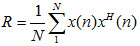
Where E[.] denotes the expectation operator. The correlation matrix R is defined as
 |
(5) |
Generally, it is assumed that the array system platform is located in the far field of targets, and then the directional signal from scattering of targets is induced with array as plane wave. By the array antenna theory, the k-th source measured at one of the element of array is given by
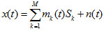 |
(6) |
As definition in [12L. Ehrenberg, S. Gannot, A. Leshem, and E. Zehavi, "Sensitivity analysis of MVDR and MPDR beamformers", IEEE 26th Convention of Electrical and Electronics Engineering, Israel, 2010.
[http://dx.doi.org/10.1109/EEEI.2010.5662190] ], the steering vector of echoes are represented as
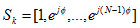 |
(7) |
Where  is the phase delay. By introducing (4) and (7) into (5), correlation matrix R can be simply rewritten as
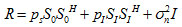 |
(8) |
Where So is the desired signal steering vector, and  are the power of the uncorrelated impinging desired signal, interference and noise, respectively.
From the aforementioned analysis, the array system output power can be expressed as
 |
(9) |
2.2. Array Output Parameter
1) Beam Pattern
Weight of CBF is a static response to the elements of the array system. In contrast, the weight of MVDR is adaptive on the array sample data, and it can be optimized with maximum impulse response to the desired direction of arrival. In this beamformer, array system can achieve minimum output power and maximum signal-interference-noise ratio (SINR). Generally, CBF's weight is defined as
 |
(10) |
MVDR’s weight can be derived from the following linearly constrained quadratic problem [13D.L. Duttweiler, "Proportionate normalized least-mean-squares adaptation in echo cancelers", IEEE Trans. Speech Audio Process., vol. 8, no. 5, pp. 508-518, 2000.
[http://dx.doi.org/10.1109/89.861368] ] as
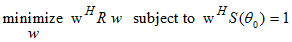 |
(11) |
Then the solution of (11) by least square method is performed as
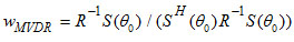 |
(12) |
By referring to [14L.C. Godara, Smart Antenna., CRC Press: Boca Raton, FL, 2004, pp. 29-30.
[http://dx.doi.org/10.1201/9780203496770] ] and using matrix Inversion Lemma, the correlation matrix R can be replaced by data snapshots and expressed as
 |
(13) |
Where n is snapshot number of data, N is channel number.
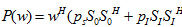
2) Output Power and Array Gain
Assuming that noise and interference are uncorrelated, by introducing (10) and (12) into (9), respectively, the output power for both CBF and MVDR beamformer is expressed as (14) and (15), respectively
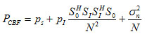 |
(14) |
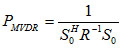 |
(15) |
Similarly, SINR for both CBF and MVDR beamformer can be obtained as [15J. Ward, H. Cox, and S. Kogon, "A comparison of robust adaptive beamforming algorithms", In: Conference Record of the Thirty-Seventh Asilomar Conference on Signals, Systems and Computers, California, USA, 2003, pp. 1340-1344.
[http://dx.doi.org/10.1109/ACSSC.2003.1292206] ]
 |
(16) |
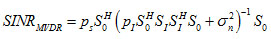 |
(17) |
According to the [16H.L. Trees, Optimum Array Processing: Part IV of Detection, Estimation, and Modulation Theory., Wiley: New York, 2002, pp. 1200-1210.
[http://dx.doi.org/10.1002/0471221104] ], array gain for both CBF and MVDR beamformer can be derived as (18) and (19), respectively
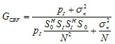 |
(18) |
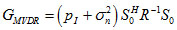 |
(19) |
Fig. (1 ) shows the beam pattern of output signal about CBF and MVDR beamformer. The case is that the degree of arrival (DOA) of clutter is ±40º, and the steering direction is 0º, number of linear array antenna is 8, central frequency of half wavelength antenna is 150 MHz, and element distance is half wavelength. As shown in Fig. (1), MVDR method has a deeper null level of interference degree and performs better than CBF more than 30 dB. It means that MVDR beamformer can decrease the clutter at the interference degree.
 |
Fig. (1) Beam pattern of CBF and MVDR beamformer. |
3. EFFECT OF ERROR ANALYSIS
3.1. Effect of Weight Vector Errors
Assuming that the error happens to weights of beamformer and follows statistics as (20), and mean output power and SINR can be analyzed by [10L.C. Godara, "Error analysis of the optimal antenna array processors", IEEE Trans. Aerosp. Electron. Syst., vol. AES-22, no. 4, pp. 395-409, 1986.
[http://dx.doi.org/10.1109/TAES.1986.310775] ]
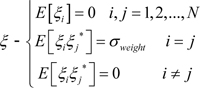 |
(20) |
 |
(21) |
 |
(22) |
By introducing (10), (12), (21) and (22) into (9), the output power of signal can be rewritten as (23) and (24), respectively
 |
(23) |
 |
(24) |
Taking the mean value on both sides in (23) and (24), the mean output power of CBF and MVDR beamformer about signal can be expressed as (25) and (26), respectively
 |
(25) |
 |
(26) |
Similarly, the mean output power of CBF and MVDR beamformer about interference and noise are given by (27) and (28), respectively
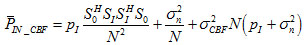 |
(27) |
 |
(28) |
Obviously, the output SINR of CBF and MVDR beamformer can be defined as (29) and (30)
 |
(29) |
 |
(30) |
To study the error effects of beamformer, the SINR has been compared by both CBF and MVDR method with the same parameters of array system. To simply analytical process, assuming,
 the input SIR is equal to 0 dB, 20 dB and 40 dB, respectively. Weight fluctuation is considered to follow statistics characteristics as (20). In Figs. (2
 and 3
and 3 ), the output SINR of CBF and MVDR beamformer with different input SIR has been simulated. It shows that output SINR of array system becomes worse with weight fluctuating increasing, and they have maximum SINR when errors of weight are equal to zero. Compared to CBF beamformer, the SINR of MVDR beamformer has a higher value when weight error is equal to zero. They have the same tendency of SINR as weight error changes. The output SINR is down from 30 dB to 0 dB with weight error increasing from 0 to 0.2. It is obvious that the SINR of both MVDR and CBF beamformer have better performance when the input SIR gets bigger. It means that the array system could get higher output SINR with the input SIR increasing. However, they both perform not well when variance of weight becomes larger. Kinds of reasons may cause the weight vector error, such as uncertainty in the positions of array elements, assuming the plane wave arrives at the array and makes errors in the steering vector or phase. The numbers of snapshots for calculating the correlation matrix may also cause weight errors. The output SINR is sensitive to the weight fluctuation from the simulation in Fig. (2) and Fig. (3). It indicates that both MVDR and CBF beamformer should get accurate weight to avoid output SINR becoming worse.
 |
Fig. (2) Output SINR of CBF beamformer with error of weight vector. |
 |
Fig. (3) Output SINR of MVDR beamformer with error of weight vector. |
3.2. Effect of Steering Vector Errors
One reason for errors of steering vector is that the array system of platform can’t be steady all the time especially in high-altitude radar for air turbulence. Assuming that variance of steering vector is distributed the same as (20), both CBF and MVDR beamformer have the same steering vector errors with correlation spectral
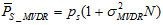
 . From (9), we can get the desired signal and clutter mean output power of CBF beamformer expressed as
 |
(31) |
 |
(32) |
Where  Then SINR and gain of CBF beamformer can be given by
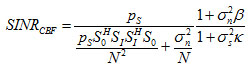 |
(33) |
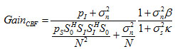 |
(34) |
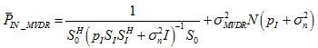
Signal-Plus-Noise matrix inverse processor is used for calculating weight of MVDR and it can be also replaced by Noise matrix inverse as previously mentioned. Defining, 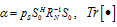 denotes the trace of
  . The output SINR and gain of MVDR beamformer can be expressed as
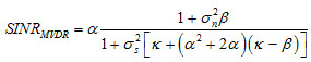 |
(35) |
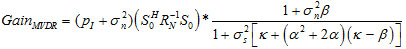 |
(36) |
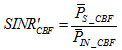
The output SINR for both CBF and MVDR beamformer with error of steering vector is shown in Figs. (4 and 5
and 5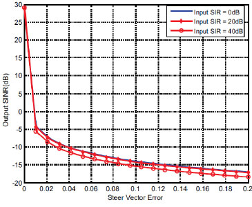 ). It can be seen that the output SINR of CBF beamformer declines slowly as variance of steering vector becomes larger. In contrast, output SINR of MVDR beamformer declines quickly with linear change as steering vector variance changes from 0 to 0.2. It means that the MVDR method is more sensitive to variance of steering vector than that of CBF beamformer. Moreover, From (33) and (35) one can know that the denominator of SINRMVDR has
  which does not exist in SINRCBF. The algebraic term leads to the output SINR of MVDR drops quickly.
 |
Fig. (4) Output SINR of CBF beamformer with error of steering vector. |
 |
Fig. (5) Output SINR of MVDR beamformer with error of steering vector. |
CONCLUSION
Interference and noise could mask the target signal in the array radar system, and the MVDR method can achieve outstanding performance to decrease the clutter at the degree of arrival. However, output SINR that are related to errors of weight and steering vector, may affect the beamformer performance. Error analysis is applied by both MVDR and CBF beamformer method. Through building signal model and deriving the parameters of array system, the SINR of MVDR and CBF is further studied. As compared to CBF beamformer, MVDR is more robust and sensitive to decrease clutter. Furthermore, SINR of MVDR beamformer changes more quickly with the steering vector increasing. Because the scenario couldn’t be ideal in engineering application, the performance of robust beamforming techniques should also be studied with some variation on weight vector. Considering effects of perturbation with kinds of factors and improving the robust characteristics of MVDR for processing complex scenario, which are our future work.
CONFLICT OF INTEREST
The authors confirm that this article content has no conflict of interest.
ACKNOWLEDGEMENTS
This work has been supported by the National Basic Research Program of China (“863”Program) of Grant 2012AA061403, Science and Technology Program of Henan of Grant 162102210266 and Doctoral Scientific Research Start-up Foundation of Henan Normal University of Grant 5101029170276.
REFERENCES
| [1] | J. Capon, "High-resolution frequency-wave number spectrum analysis", Proc. IEEE, vol. 57, no. 8, pp. 1408-1418, 1969. [http://dx.doi.org/10.1109/PROC.1969.7278] |
| [2] | S.A. Kassam, and H.V. Poor, "Robust techniques for signal processing: A survey", Proc. IEEE, vol. 73, no. 3, pp. 433-481, 1985. [http://dx.doi.org/10.1109/PROC.1985.13167] |
| [3] | R. Lorenz, and S. Boyd, "Robust minimum variance beamforming", IEEE Trans. Signal Process., vol. 53, no. 5, pp. 1684-1696, 2005. [http://dx.doi.org/10.1109/TSP.2005.845436] |
| [4] | F. Ahmad, and M. Amin, "High-resolution imaging using Capon beamformers for urban sensing applications", In: Proceedings of the IEEE International Conference on Acoustics, Speech and Signal Processing (ICASSP 2007), 2007, pp. II-985-II-988. [http://dx.doi.org/10.1109/ICASSP.2007.366403] |
| [5] | F. Ahmad, G. Frazer, S. Kassam, and M. Amin, "Design and implementation of near-field, wideband synthetic aperture beamformers", IEEE Trans. Aerosp. Electron. Syst., vol. 40, no. 1, pp. 206-220, 2004. [http://dx.doi.org/10.1109/TAES.2004.1292154] |
| [6] | F.L. Liu, and J.K. Wang, "Robust MVDR beamformer for nulling level control via multi-parametric quadratic programming", Prog. Electromagn. Res. C, vol. 20, pp. 239-254, 2011. [http://dx.doi.org/10.2528/PIERC11022507] |
| [7] | B. Carlson, "Covariance matrix estimation errors and diagonal loading in adaptive arrays", IEEE Trans. Aerosp. Electron. Syst., vol. 24, no. 4, pp. 397-401, 1988. [http://dx.doi.org/10.1109/7.7181] |
| [8] | J. Li, P. Stoica, and Z. Wang, "On robust capon beamforming and diagonal loading", IEEE Trans. Signal Process., vol. 51, no. 7, pp. 1702-1715, 2003. [http://dx.doi.org/10.1109/TSP.2003.812831] |
| [9] | G. Liang, K. Liu, and W. Lin, "A new beam-forming algorithm based on flank acoustic vector-sensor array sonar", In: International Conference on Wireless Communications & Signal Processing, Nanjing, China, 2009, pp. 1-5. [http://dx.doi.org/10.1109/WCSP.2009.5371393] |
| [10] | L.C. Godara, "Error analysis of the optimal antenna array processors", IEEE Trans. Aerosp. Electron. Syst., vol. AES-22, no. 4, pp. 395-409, 1986. [http://dx.doi.org/10.1109/TAES.1986.310775] |
| [11] | M. Wax, and Y. Anu, "Performance analysis of the minimum variance beamformer in the presence of steering vector errors", IEEE Trans. Signal Process., vol. 44, pp. 938-947, 1996. [http://dx.doi.org/10.1109/78.492546] |
| [12] | L. Ehrenberg, S. Gannot, A. Leshem, and E. Zehavi, "Sensitivity analysis of MVDR and MPDR beamformers", IEEE 26th Convention of Electrical and Electronics Engineering, Israel, 2010. [http://dx.doi.org/10.1109/EEEI.2010.5662190] |
| [13] | D.L. Duttweiler, "Proportionate normalized least-mean-squares adaptation in echo cancelers", IEEE Trans. Speech Audio Process., vol. 8, no. 5, pp. 508-518, 2000. [http://dx.doi.org/10.1109/89.861368] |
| [14] | L.C. Godara, Smart Antenna., CRC Press: Boca Raton, FL, 2004, pp. 29-30. [http://dx.doi.org/10.1201/9780203496770] |
| [15] | J. Ward, H. Cox, and S. Kogon, "A comparison of robust adaptive beamforming algorithms", In: Conference Record of the Thirty-Seventh Asilomar Conference on Signals, Systems and Computers, California, USA, 2003, pp. 1340-1344. [http://dx.doi.org/10.1109/ACSSC.2003.1292206] |
| [16] | H.L. Trees, Optimum Array Processing: Part IV of Detection, Estimation, and Modulation Theory., Wiley: New York, 2002, pp. 1200-1210. [http://dx.doi.org/10.1002/0471221104] |