- Home
- About Journals
-
Information for Authors/ReviewersEditorial Policies
Publication Fee
Publication Cycle - Process Flowchart
Online Manuscript Submission and Tracking System
Publishing Ethics and Rectitude
Authorship
Author Benefits
Reviewer Guidelines
Guest Editor Guidelines
Peer Review Workflow
Quick Track Option
Copyediting Services
Bentham Open Membership
Bentham Open Advisory Board
Archiving Policies
Fabricating and Stating False Information
Post Publication Discussions and Corrections
Editorial Management
Advertise With Us
Funding Agencies
Rate List
Kudos
General FAQs
Special Fee Waivers and Discounts
- Contact
- Help
- About Us
- Search


The Open Electrical & Electronic Engineering Journal
(Discontinued)
ISSN: 1874-1290 ― Volume 13, 2019
Mechanical and Electromagnetic Analysis of High Speed Motor/Generator for Electric Turbo Compounding System
Bongseok Choi, Donghoon Jung, Jaek wang Lee, Ju Lee*
Abstract
Background:
Recently, environment friendly technologies are being introduced as global warming is rapidly progressing. One of the effective way to reduce the problem, Electric Turbo Compounding System has been researched globally. With this system, about 30% exhaust gas can be recycled as a power source. Therefore, this system is effective for engine systems with purposes such as downsizing and increasing efficiency of the system.
Objective & Method:
Surface mounted Permanent Magnet Motor is applied to this system due to its high efficiency, power density, small size, and low weight. However, during high speed operation, a retaining sleeve is essential in rotor such as Inconel 718 to satisfy a mechanical safety factor of the rotor. In this paper, through basic theory, the sleeve thickness is predicted according to the permanent magnet dimension and minimum sleeve thickness is determined satisfying mechanical safety factor by mechanical analysis. Furthermore, by electromagnetic analysis output characteristics according to the permanent magnet dimension having same constraints such as volume, current density, current and flux distribution are compared.
Result & Conclusion:
Based on the results of the electromagnetic analysis and mechanical analysis, the appropriate ratio of electric and magnetic loading is determined with equivalent constraint condition. Consequently, only model 2 satisfies the requirement at rated and maximum speed within the current limit.
Article Information

Identifiers and Pagination:
Year: 2018Volume: 12
First Page: 121
Last Page: 131
Publisher Id: TOEEJ-12-121
DOI: 10.2174/1874129001812010121
Article History:
Received Date: 31/3/2018Revision Received Date: 26/6/2018
Acceptance Date: 10/10/2018
Electronic publication date: 28/12/2018
Collection year: 2018
open-access license: This is an open access article distributed under the terms of the Creative Commons Attribution 4.0 International Public License (CC-BY 4.0), a copy of which is available at: https://creativecommons.org/licenses/by/4.0/legalcode. This license permits unrestricted use, distribution, and reproduction in any medium, provided the original author and source are credited.
* Address correspondence to this author at the Department of Electrical Engineering, Hanyang University, Seoul, Korea, Tel: +822-2220-0342, Fax: +822-2295-7111; E-mail: julee@hanyang.ac.kr
| Open Peer Review Details | |||
|---|---|---|---|
| Manuscript submitted on 31-3-2018 |
Original Manuscript | Mechanical and Electromagnetic Analysis of High Speed Motor/Generator for Electric Turbo Compounding System | |
1. INTRODUCTION
In Paris Climate Conference 2015, 195 countries in the world have made an agreement to restrict the global average temperature rise below 2 °C, with a requirement of below 1.5 °C above the pre-industrial level [1European commission, "The Road from Paris: Assessing the implications of the paris agreement and accompanying the proposal for a Council decision on the signing, on behalf of the European Union, of the Paris agreement adopted under the United Nations framework convention on climate change", Available at: http://eur-lex.europa.eu/ legal-content/EN/TXT/?uri=CELEX: 52016DC0110]. Many countries have been trying to reduce greenhouse gas emission effectively. Transportation fields account for about 23% of greenhouse gas emissions specially in diesel engine [2"Eurostat, Greenhouse gas emission statistics – emission inventories", Available at: http://ec.europa.eu/eurostat/ statistics-explained/index.php/Greenhouse_gas_emission_ statistics_-_emission_inventories]. The fuel consumption reduction in transportation fields is a critical issue in the whole world. One of the effective way to reduce fuel consumption and Electric Turbo Compounding System (E-TCS) has been researched globally. The overall system of E-TCS is shown in Fig. (1 ). During low engine speed, since the energy from exhaust gas is insufficient, additional power source is required. In this case, the motor assists the compressor and therefore dynamic characteristic and output of engine is increased. On the other hand, during high engine speed, since excessive exhaust gas is generated, through generator, surplus energy from the gas efficiently converts mechanical energy into electrical energy, which is then stored into the battery. Therefore, since compared to conventional engine, the exhaust gas is used efficiently, it is effective in reducing greenhouse gas. Surface Mounted Permanent magnet Motor (SPM) is considered a suitable candidate for E-TCS due to high efficiency and power density, small size and low weight. On the other hand, in case of super high speed motor, due to the limitation of carrier frequency of inverter, the number of poles should be minimized [3L. Zhao, C. Ham, L. Zheng, T. Wu, K. Sundaram, J. Kapat, and L. Chow, "A Highly efficient 200000 RPM permanent magnet motor system", IEEE Trans. Magn., vol. 43, no. 6, pp. 2528-2530.
[http://dx.doi.org/10.1109/TMAG.2007.893523] ]. Furthermore, additional sleeve material is essential to protect permanent magnet (PM) from scattering by the tangential force during high speed operation. The sleeve material should be non-conductive to minimize eddy current losses. For this purpose, Inconel 718 has been adopted as sleeve material in this paper for its low conductivity and high tensile strength. Depending on the PM diameter and rotor speed, the sleeve may be needed to limit the tangential force stress [4F. Zhang, G. Du, T. Wang, G. Liu, and W. Cao, "Rotor retaining sleeve design for a 1.12-MW high-speed PM machine", IEEE Trans. Ind. Appl., vol. 51, no. 5, pp. 3675-3685.
[http://dx.doi.org/10.1109/TIA.2015.2423659] ]. However, since the permeability of the sleeve is same as airgap, the sleeve thickness should be minimized. Therefore, through mechanical analysis, appropriate sleeve thickness is needed to be determined. Furthermore, with same constraints such as current density, current and volume, the output performances are different according to the ratio of loading. Therefore, appropriate model is applied to the E-TCS by electromagnetic analysis. In this paper, optimized motor is designed to satisfy mechanical constraint and electromagnetic requirement. In Section II, constraint condition and requirement of the motor are presented. Furthermore, overall process of the motor for E-TCS is suggested. In Section III, different rotor models that satisfy mechanical safety factor more than 1.6 according to the thickness of PM and sleeve are predicted by the basic theory. Furthermore, each model is analyzed by FEM. In Section IV, output characteristics of the models from Section III with same conditions are compared.
 |
Fig. (1) Cross section of E-TCS. |
2. OBJECTIVE & METHOD:
2.1. Section II – Constraint & Requirement
The constraints of motor/generator for E-TCS are presented in Table 1. Due to operating at super high speed, carrier frequency of inverter constrains the number of pole. In Fig. (2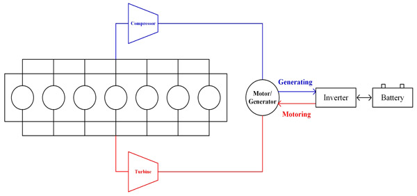 ) E-TCS due to the constraint of limited inverter carrier frequency, the pole of the motor is selected as 2. Furthermore, minimum safety factor is set as 1.6 in this paper. For material of PM, because of the high operation temperature, the SmCo (2:17) is used which has great performance for demagnetization in high temperature.
 |
Fig. (2) Design process of the motor for E-TCS. |
2.2. Section III – Structure Analysis
2.2.1. Theory
Since the PM material exhibits poor mechanical characteristics, in SPM, the retaining sleeve is necessary [5N. Bianchi, S. Bolognani, and F. Luise, "Potentials and limits of high-speed PM motors", IEEE Trans. Ind. Appl., vol. 40, no. 6, .
[http://dx.doi.org/10.1109/TIA.2004.836173] ]. Considerable candidates for the sleeves are non-ferromagnetic and have high yield stresses. The electric conductivity of the Inconel 718 is which is 2.5 times lower than 35PN230. Furthermore, due to high yield strength, the Inconel 718 is appropriate to use as sleeve in SPM. Before manufacturing super high speed motor, securing enough safety factor that describes the load carrying capacity of a system beyond the expected loads is important to keep the PM from scattering. The PM diameter and thickness of the sleeve is important to determine the safety factor. The cross section of the rotor is presented in Fig. (3 ). The pressure when the rotor rotates is proportional to the diameter of the PM and rotation velocity of the motor. The following equation (1) explains relationship among variables.
 |
Fig. (3) 2D cross section of the rotor. |
 |
(1) |
At the outer radius, r = R1,
 |
(2) |
At the inner radius, r = R2,
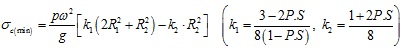 |
(3) |
Where
σ c: Inner pressure of the motor (Mpa)
σ c(max): Maximum inner pressure (Mpa)
σ c(min): Minimum inner pressure (Mpa)
p: Mass density (g/cm3)
ω: Angular speed (rad/s)
g: Gravitational acceleration (kgm/s2)
R1: Inner radius (mm)
R2: Outer radius (mm)
r:
 (mm)
(mm)
P.S: Poisson’s ratio
The inner pressure of the rotor is proportional to radius of the motor and proportional to the square of rotational speed of the motor. In this paper, initially three rotor models are selected.
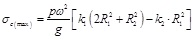
In Table (2) based on equation (2), maximum inner pressure of the PM which is generated -at the end- of the circle is presented for three models. As presented in Fig. (4 ). the forces caused by the inner pressure is generated called circumferential stress or tangential stress. As mentioned before, for high speed operation, the retaining sleeve is necessary to the SPM to protect the PM from the forces by the inner pressure (Table 3). The forces caused by pressure is related to the inner pressure and the volume of the magnet as following equation (4).
 |
(4) |
 |
Fig. (4) 3D cross section of the motor. |
When the sleeve -exists- around the PM, the total tension in the sleeve is expressed as following equation.
 |
(5) |
 |
(6) |
 |
(7) |
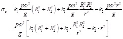
From equation (5), (6), (7) and (8), the tangential stress in sleeve is expressed as following equation (9).
 |
(8) |
 |
(9) |
Furthermore, safety factor is calculated as following equation (10).
 |
(10) |
Where
F: The forces generated by the inner pressure (Mpa)
A: Sleeve area (mm2)
D: The diameter of PM (mm)
L: Axial length (mm)
T: Total tension in the sleeve (Mpa)
t: The thickness of the sleeve (mm)
σt(max): Tangential stress of the sleeve (Mpa)
S.F: Safety factor
σt: Maximum tangential stress of the sleeve (Mpa)
TS;inconel 718: Tensile strength of the inconel 718 (Mpa)
The tangential stress of the sleeve is proportional to the diameter of the magnet and the inner pressure and inversely proportional to the sleeve thickness. Minimum sleeve thickness which satisfies safety factor more than 1.6 according to the diameter of magnet is calculated by equation (10). According to the sleeve thickness, tangential stress and safety factor for PM diameter 20mm are shown in Table 4.
2.2.2. Simulation
In the previous section 3.1, appropriate sleeve thickness that satisfies safety factor constraint according to the magnet diameter is predicted (Table 5). In this section each models are simulated by FEM with following assumptions [6L. Yi, Y. Pei, P. Liang, and C. Feng, "Analysis of the rotor mechanical strength of interior permanent magnet synchronous in-wheel motor with high speed and large torque", 2014 IEEE Conference and Expo Transportation Electrification Asia-pacific, pp. 1-5.].
- Constant speed in the steady state (maximum speed)
- Thermal effects neglected;
- Yield indicated by planar Von Mises st
- Electromagnetic force considered negligible;
- Rotor eccentricity and vibration neglected
In Figs. (5 , 7
, 7 and 9
and 9 ), the analysis result of the inner pressure of the magnet and in Figs. (6
 , 8
, 8 and 10
 ) the results of tangential stress in the sleeve according to PM -diameter are shown-.
 |
Fig. (5) PM 20 mm. |
 |
Fig. (6) PM 20 mm / sleeve 0.65 mm. |
 |
Fig. (7) PM 30 mm. |
 |
Fig. (8) PM 30 mm / sleeve 2.4 mm. |
 |
Fig. (9) PM 35 mm. |
 |
Fig. (10) PM 35 mm / sleeve 4 mm. |
2.3. Section IV – Electromagnetic Analysis
The main objective of this section is to compare the output characteristic of the different rotors. From same stator constraint of the outer diameter, as the magnet and sleeve thickness increased, the slot area of the stator should be changed. Therefore, the number of turns of the coil is changed according to the rotors. Furthermore, for equivalent comparison, the yoke thickness and teeth width is needed to be adjusted according to the number of turns. In Figs. (11 ~13
~13 ) the flux density distribution is shown according to the different models. All models have almost same flux distribution on the yoke and teeth in order to apply same constraint condition. Additionally, the slot area for the coils is calculated by same current density and current respectively. With same constraints three different PM machines are investigated and compared.
 |
Fig. (11) PM 20 mm. |
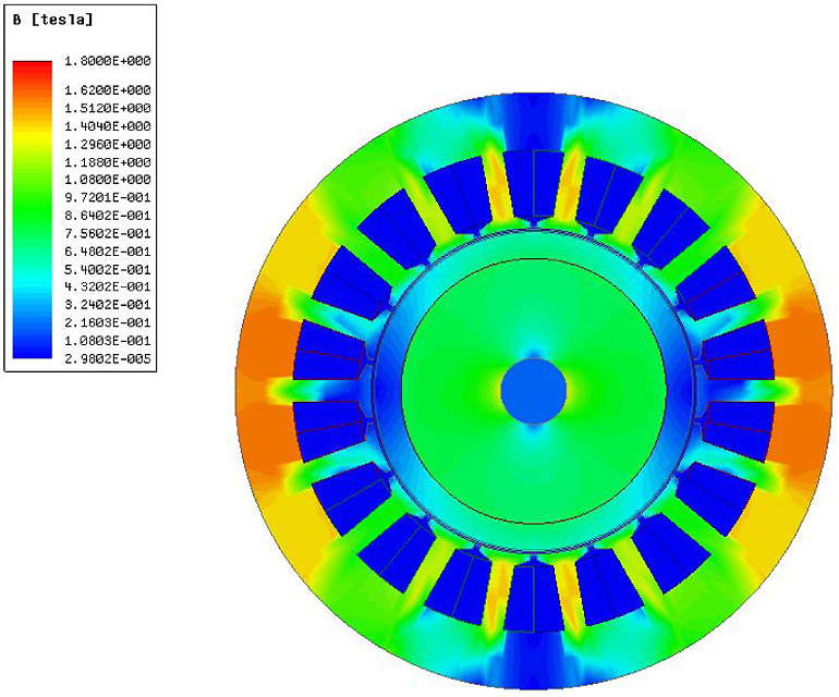 |
Fig. (12) PM 30 mm. |
 |
Fig. (13) PM 35 mm. |
2.3.1. Machine Losses
1) Copper Loss: The copper loss dealt with this paper concerns the dc loss only. AC loss due to skin and proximity effects is neglected. Analytically, the copper loss for one phase can be determined as equation (11)
 |
(11) |
The winding resistance calculation expression is given as equation (12)
 |
(12) |
Where
Irms: Current (rms)
R: Phase resistance (ohm)
lω: The average turn length (mm)
Nω: The number of turns per phase
pcu: The specific resistance of copper [ohm]
AC: The slot area (mm2)
In Table 6, copper loss at rated speed is presented. The copper loss which is relatively influential element to the efficiency at low speed is the smallest in model 2 due to low phase resistance and current value Table 7.


2) Core Losses: The core loss is composed of the the eddy-current loss and the hysteresis loss, and can be approximately expressed as equation (13) (Table 8).
 |
(13) |
Where
f: The frequency [Hz]
Kn: Constant eddy current loss coefficient
Ke: Constant hysteresis loss coefficient

2.3.2. Torque & Efficiency
Except for the mechanical losses, the overall losses that are determined in the previous sections are considered to drive the machine efficiency. In Table 9, the efficiency of three machine types is compared. For model 2, the machine efficiency is higher than the other models at the rated speed. Furthermore, as rated torque is 2.39, only model 2 satisfies the requirement (Table 10).


RESULT AND CONCLUSION
This paper has dealt with the mechanical and electromagnetic analysis of three different models according to the magnet and sleeve thickness for E-TCS motor/generator. Since the inner pressure of the magnet is proportional to the square of the rotational speed, in very high speed, securing enough sleeve thickness is important. However, as sleeve material has the same permeability as airgap, thickness should be minimized to increase torque density. From mechanical analysis, optimized sleeve thickness is determined according to the magnet dimensions. Furthermore, in limited volume condition, as the rotor dimension increases, the slot area of the stator is needed to be decreased. Based on the results of the electromagnetic analysis, the appropriate ratio of electric and magnetic loading -is- determined with equivalent constraint condition. Consequently, only model 2 -satisfies- the requirement at rated and maximum speed within the current limit.
CONFLICT OF INTEREST
This work was supported by the National Research Foundation of Korea (NRF) grant funded by the Korean government (MSIP) (No. 2016R1A2A1A05005392)
ACKNOWLEDGEMENTS
Declared none
REFERENCES
| [1] | European commission, "The Road from Paris: Assessing the implications of the paris agreement and accompanying the proposal for a Council decision on the signing, on behalf of the European Union, of the Paris agreement adopted under the United Nations framework convention on climate change", Available at: http://eur-lex.europa.eu/ legal-content/EN/TXT/?uri=CELEX: 52016DC0110 |
| [2] | "Eurostat, Greenhouse gas emission statistics – emission inventories", Available at: http://ec.europa.eu/eurostat/ statistics-explained/index.php/Greenhouse_gas_emission_ statistics_-_emission_inventories |
| [3] | L. Zhao, C. Ham, L. Zheng, T. Wu, K. Sundaram, J. Kapat, and L. Chow, "A Highly efficient 200000 RPM permanent magnet motor system", IEEE Trans. Magn., vol. 43, no. 6, pp. 2528-2530. [http://dx.doi.org/10.1109/TMAG.2007.893523] |
| [4] | F. Zhang, G. Du, T. Wang, G. Liu, and W. Cao, "Rotor retaining sleeve design for a 1.12-MW high-speed PM machine", IEEE Trans. Ind. Appl., vol. 51, no. 5, pp. 3675-3685. [http://dx.doi.org/10.1109/TIA.2015.2423659] |
| [5] | N. Bianchi, S. Bolognani, and F. Luise, "Potentials and limits of high-speed PM motors", IEEE Trans. Ind. Appl., vol. 40, no. 6, . [http://dx.doi.org/10.1109/TIA.2004.836173] |
| [6] | L. Yi, Y. Pei, P. Liang, and C. Feng, "Analysis of the rotor mechanical strength of interior permanent magnet synchronous in-wheel motor with high speed and large torque", 2014 IEEE Conference and Expo Transportation Electrification Asia-pacific, pp. 1-5. |
| [7] | G. Dajaku, H. Hofmann, F. Hetemi, X. Dajaku, W. Xie, and D. Gerling, "Comparison of two different IPM traction machines with concentrated winding", IEEE Trans. Ind. Electron., vol. 63, no. 7, pp. 4137-4149. [http://dx.doi.org/10.1109/TIE.2016.2544720] |