- Home
- About Journals
-
Information for Authors/ReviewersEditorial Policies
Publication Fee
Publication Cycle - Process Flowchart
Online Manuscript Submission and Tracking System
Publishing Ethics and Rectitude
Authorship
Author Benefits
Reviewer Guidelines
Guest Editor Guidelines
Peer Review Workflow
Quick Track Option
Copyediting Services
Bentham Open Membership
Bentham Open Advisory Board
Archiving Policies
Fabricating and Stating False Information
Post Publication Discussions and Corrections
Editorial Management
Advertise With Us
Funding Agencies
Rate List
Kudos
General FAQs
Special Fee Waivers and Discounts
- Contact
- Help
- About Us
- Search


The Open Mechanical Engineering Journal
(Discontinued)
ISSN: 1874-155X ― Volume 14, 2020
Preparation and Testing of PAN Carbon/Epoxy Resin Composites
Brundaban Patro1, *, D. Shashidhar2, B. Rajeshwer2, Saroj Kumar Padhi3
Abstract
Background:
Due to light weight, high performance and excellent mechanical properties, carbon fibers are considered a key material in the 21st century. These are extensively used in many industries for structural usages, such as aerospace, aeronautical, sporting goods applications, and automotive and medical devices, due to their desirable strength to weight properties. Now, these are globally accepted as a high performance and high-strength material. Most of the carbon fibers are derived from polyacrylonitrile fiber precursor. These materials have the potential for fire hazards caused due to heat, smoke, and electric short circuit.
Objective:
To prepare polyacrylonitrile carbon and epoxy resin laminates in multilayers by hand-lay-up method and testing by ASTM (American Society for Testing and Materials) standards.
Method:
Polyacrylonitrile carbon fiber/epoxy resin composites are prepared using the hand-lay-up method. For the non-destructive testing, the ultrasonic type is used. For the destructive testing, a universal testing machine is used to test the tensile test, the flexural test and the inter-laminar shear stress test, as per the ASTM standard. Subsequently, the physical properties, such as the density test and the fiber content, the resin content and the void content tests of the laminate are carried out.
Results:
The experimental results show that the matrix laminates have good mechanical and physical properties.
Conclusion:
Preparation and testing of polyacrylonitrile carbon/epoxy resin composites are carried out and the prepared laminates exhibit good mechanical and physical properties. Hence, the laminates can be used in many industrial and commercial applications, as a composite material.
Article Information

Identifiers and Pagination:
Year: 2017Volume: 11
First Page: 14
Last Page: 24
Publisher Id: TOMEJ-11-14
DOI: 10.2174/1874155X01711010014
Article History:
Received Date: 02/03/2017Revision Received Date: 22/03/2017
Acceptance Date: 24/04/2017
Electronic publication date: 21/06/2017
Collection year: 2017
open-access license: This is an open access article distributed under the terms of the Creative Commons Attribution 4.0 International Public License (CC-BY 4.0), a copy of which is available at: (https://creativecommons.org/licenses/by/4.0/legalcode). This license permits unrestricted use, distribution, and reproduction in any medium, provided the original author and source are credited.
* Address correspondence to this author at the National Institute of Technology Warangal, Mechanical Engineering Department, Warangal, Telangana, 506004, India, E-mail: bpatro111@gmail.com
| Open Peer Review Details | |||
|---|---|---|---|
| Manuscript submitted on 02-03-2017 |
Original Manuscript | Preparation and Testing of PAN Carbon/Epoxy Resin Composites | |
1. INTRODUCTION
Due to light weight, high performance and excellent mechanical properties, carbon fibers are considered a key material in the 21st century. These are extensively used in many industries for structural usages, such as aerospace, aeronautical, sporting goods applications, and automotive and medical devices, due to their desirable strength to weight properties. Now, these are globally accepted as a high performance and high-strength material. Most of the carbon fibers are derived from polyacrylonitrile (PAN) fiber precursor. These materials have the potential for fire hazards caused due to heat, smoke, electric short circuit, etc. The advanced growth of composite materials finds suitable applications in the above-mentioned areas.
In the literature, many researchers studied the characterization and thermo-physical properties of laminar composites. Paiva et al. [1J. Paiva, S. Mayer, and M. Rezende, "Comparison of tensile strength of different carbon fabric reinforced epoxy composites", Mater. Res., vol. 9, no. 1, pp. 83-90, 2006.] compared the tensile strength of various laminar composites, made of carbon fiber and epoxy resin. The obtained results showed the adequate combination and proper reinforcement in the matrix composite. Fu et al. [2H. Fu, C. Ma, N. Kuang, and S. Luan, "Interfacial properties modification of carbon fiber/polyarylacetylene composites", Chin. J. Aeronauti., vol. 20, no. 2, pp. 124-128, 2007.] investigated the surface properties of carbon fiber/polyarylacetylene composites. They obtained remarkably modified interfacial properties between carbon fiber and non-polar polyarylacetylene after removing weak surface layers. Li et al. [3W. Li, Z. Chen, J. Li, X. Chen, H. Xuan, and X. Wang, "Preparation of PAN/phenolic-based carbon/carbon composites with flexible towpreg carbon fiber", Mater. Sci. Eng. A, vol. 485, no. 1-2, pp. 481-486, 2008.] studied the structural characteristics and flexural strength of PAN/phenolic based composites. In their tests, they noticed improved flexural strength when the number of densification cycles was increased. Muthusamy and Chung [4S. Muthusamy, and D.D. Chung, "Carbon-fiber cement based materials for electromagnetic shielding", ACI Mater. J., vol. 107, no. 6, pp. 602-610, 2010.] carried out detailed studies related to the carbon fiber and cement based composites. They noticed increment in flexural strength and modulus with increasing the fiber content. Banakar and Shivananda [5P. Banakar, and H.K. Shivananda, "Preparation and characterization of the carbon fiber reinforced epoxy resin composites", IOSR J. of Mec. and Civil Eng., vol. 1, no. 2, pp. 15-18, 2012.] studied the effects of fiber orientations on the laminates of carbon fiber reinforced epoxy resin composites, to affirm the mechanical properties. They confirmed that the fiber orientation largely affects the mechanical properties of the laminated composites. Venugopalan et al. [6R. Venugopalan, D. Sathiyamoorthy, and A.K. Tyagi, "Development of carbon/carbon composites for nuclear reactor applications", BARC Newsletter, vol. 325, pp. 16-20, 2012.] developed the carbon-carbon composites using PAN fiber and phenolic resin matrix for nuclear reactor applications. Their results proved that the carbon-carbon composite materials can be used in nuclear applications even at low temperatures. Srivastav et al. [7S. Srivastav, P.H. Maheshwari, R.B. Mathur, and A.K. Sharma, "Processing of carbon fiber/PFA composite material as electrode of fuel cells and batteries", Int. Archives of Sci. and Technol., vol. 13, no. 1, pp. 19-24, 2013.] studied the electrical and mechanical characterization of carbon fiber/poly-furfuryl-alcohol composites. They found that the prepared composite materials have excellent mechanical properties, and can be used as material in fuel cells. Lu et al. [8X. Lu, P. Xiao, X. Xu, and J. Chen, "Flexural destructive process of unidirectional carbon/carbon composites reinforced with in situ grown carbon nanofibers", Trans. of Nonferrous Met. Soc. of China, vol. 24, pp. 3134-3141, 2014.] studied the flexural properties of carbon-carbon composites with situ grown carbon nanofibers. They found that the flexural strength and modulus of the composite are higher due to the blockage of cracks by situ grown carbon nanofibers. Luo et al. [9H. Luo, G. Xiong, C. Ma, D. Li, and Y. Wan, "Preparation and performance of long carbon fiber reinforced polyamide 6 composites injection-molded from core/shell structured pellets", Mater. Des., vol. 64, pp. 294-300, 2014.] investigated the mechanical properties, the melting flowability and the size distribution of long carbon fiber reinforced polyamide composites, prepared by injection moulding. From their results, it was demonstrated that the melting flowability increases with an increase in the sizing concentration, while the mechanical properties achieve peak value at a specific sizing concentration (22 wt%). Chen et al. [10J. Chen, P. Xiao, and X. Xiong, "The mechanical properties and thermal conductivity of carbon/carbon composites with the fiber/matrix interface modified by silicon carbide nanofibers", Mater. Des., vol. 84, pp. 285-290, 2015.] studied the mechanical properties of carbon-carbon composites, modified with silicon carbide nanofibers. They also noticed the enhancement in thermal conductivity of the modified composites. Jia et al. [11Y. Jia, K. Li, L. Xue, J. Ren, S. Zhang, and X. Zhang, "Microstructure and mechanical properties of carbon fiber reinforced multilayered (PyC-SiC)n matrix composites", Mater. Des., vol. 86, pp. 55-60, 2015.] studied the mechanical and flexural properties of multi-layered C/(PyC-SiC) composites, prepared by vapour infiltration process. Their study revealed that the enhanced mechanical properties of the composites are due to the presence of multilayers in the matrix. Ashori et al. [12A. Ashori, S. Menbari, and R. Bahrami, "Mechanical and thermomechanical properties of short carbon fiber reinforced polypropylene composites using exfoliated graphene nanoplatelets coating", J. Ind. Eng. Chem., vol. 38, pp. 37-42, 2016.] investigated the mechanical and thermo-mechanical properties of composites of carbon fiber and polypropylene. They reported an improvement in the above properties. He et al. [13Y. He, L. Wang, and D. Jia, "Coal/PAN interconnected carbon nanofibers with excellent energy storage performance and electrical conductivity", Electrochim. Acta, vol. 194, pp. 239-245, 2016.] achieved excellence in energy storage performance and electrical conductivity by using composites of carbon and raw form of coal. Jie et al. [14C. Jie, H. Long, X. Peng, and X. Xiang, "Mechanical properties of carbon/carbon composites with the fibre/matrix interface modified by carbon nanofibers", Mater. Sci. Eng. A, vol. 656, pp. 21-26, 2016.] studied the mechanical properties and microstructure of carbon nanofiber composites. They noticed an interface layer between the fiber and the matrix. The interface layer comprises of carbon nanofibers and high textured pyrocarbon. They noticed enhanced flexural strength after modifying the interface layer by carbon nanofibers. Mokati et al. [15R. Mokati, M. Yugender, and M.S. Bala, "Polymer matrix composite materials for aerospace applications", Int. J. Emerging Res. Manage. Tech., vol. 5, no. 7, pp. 34-41, 2016.] studied the characteristics of composites of rayon carbon and glass fibers with PAN carbon, mixed with phenolic and epoxy resins. They prepared the laminates as per the ASTM standards by hand-lay-up method, and studied different properties, such as mechanical, material and thermal properties. They observed better results in these properties. Yi et al. [16J.W. Yi, W. Lee, D.G. Seong, H.J. Won, S.W. Kim, M.K. Um, and J.H. Byun, "Effect of phenoxy based coating resin for reinforcing pitch carbon fibers on the interlaminar shear strength of PA6 composites", Compos., Part A Appl. Sci. Manuf., vol. 87, pp. 212-219, 2016.] improved the infacial adhesion properties of composites of carbon fiber by polyamide, using phenoxy resin. Yoo et al. [17S. Yoo, E. Kandare, R. Shanks, M.A. Al-Maadeed, and A.A. Khatibi, "Thermo-physical properties of multifunctional glass fibre reinforced polymer composites incorporating phase change materials", Thermochim. Acta, vol. 642, pp. 25-31, 2016.] studied the preparation and thermo-physical properties of glass fiber reinforced polymer composites, incorporating phase-change materials. They found that the stability (thermal and dimensional) of the composites is greatly influenced by the concentration of phase-change materials. Yu et al. [18D. Yu, J. Bai, H. Liang, T. Ma, and C. Li, "AgI-modified TiO2 supported by PAN nanofibers: A heterostructured composite with enhanced visible-light catalytic activity in degrading MO", Dyes Pigments, vol. 133, pp. 51-59, 2016.] studied the characteristics of modified AgI-TiO2/PAN composites. They found excellent stability in the composites because of the intimate contact. Zhang et al. [19L. Zhang, G. Zhang, L. Chang, B. Wetzel, B. Jim, and Q. Wang, "Distinct tribological mechanisms of silica nanoparticles in epoxy composites reinforced with carbon nanotubes, carbon fibers and glass fibers", Tribol. Int., vol. 104, pp. 225-236, 2016.] investigated the influence of silica nanoparticles on the tribological behaviour of epoxy composites, reinforced with glass fiber, carbon fiber and carbon nanotubes. They found enhanced tribological properties for silica and short carbon fibers, and insignificant results for silica and carbon nanotubes. However, addition of silica into short glass fibers showed deterioration results. Recently, Jia et al. [20Y. Jia, K. Li, L. Xue, J. Ren, S. Zhang, and H. Li, "Mechanical and electromagnetic shielding performance of carbon fiber reinforced multilayered (PyC-SiC)n matrix composites", Carbon, vol. 111, pp. 299-308, 2017.] studied the mechanical and electromagnetic properties of multilayered matrix composites of carbon fiber and pyrocarbon silicon carbide. Their results showed enhancement in mechanical properties due to the increased number of interfaces, in turn more crack deflection and propagation.
In the literature, the preparation of composites with the help of a hand-lay-up method is rare. The hand-lay-up method is a simple and cost effective method. Carbon-carbon composites are famous for high strength and light weight [21W. Brostow, and H.E. Lobland, Materials: Introduction and Applications., John Wiley and Sons: New York, 2017.]. Again, the multi-layered composites have higher yield strength due to higher phase continuity [22J. Shen, M. Wang, J. Li, S. Guo, S. Xu, Y. Zhang, T. Li, and M. Wen, "Simulation of mechanical properties of multi-layered propylene-ethylene copolymer/ethylene 1octene copolymer composites by equivalent box model and its experimental verification", Eur. Polym. J., vol. 45, pp. 3269-3281, 2009.]. Therefore, the present study discusses the preparation in multilayers by hand-lay-up method and the testing by ASTM standards of PAN carbon and epoxy laminates. This research paper may be helpful for those researchers who want to prepare the composites with the help of hand-lay-up method, and find the relevant properties of the composites.
2. PREPARATION METHOD
The direct materials are PAN carbon fiber, epoxy resin (Epofine-1555) and hardener (Finehard-5200). The properties of PAN carbon fiber are shown in Table 1. The indirect raw materials are mould, emery paper, acetone and wax polish. A metal split mould is prepared for this purpose. As compared to the ordinary mould, the metal split mould is best to remove the specimen. Then, the mould surface is cleaned by using emery paper of grade 220 and 320. Subsequently, the mould is cleaned with acetone to confirm that there is no left out resin on the mould surface. Otherwise, it could damage the laminates. Then, releasing agent, i.e., the wax polish is applied to remove the laminate from the mould after the curing process. The mould, after cleaning and applying the wax polish, is shown in (Fig. 1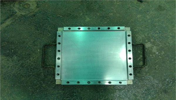 ).
).
 |
Fig. (1) Mould after cleaning and applying the wax polish. |
The PAN carbon fiber is taken at the specified sizes for the impregnating process. The mat is weighed with and without the resin content, after cutting into the specified sizes. For 250 mm x 250 mm laminate size, the mat weight is 25 grams without the resin and 65 grams with the resin. For 150 mm x 150 mm laminate size, the mat weight is 10 grams without the resin and 25 grams with the resin.
The mixture of the resin and the hardener (equal to the weight of the fiber) is prepared. The resin and hardener are taken in the ratio of 100:27; the mixture is taken into the beaker and stirred well, for the proper mixing of the hardener and the resin. The Epofine resin is 600 g/cm3, and the hardener is 162 g/cm3. The mixture made is then applied to the fiber mat thoroughly with no gaps left, covering the fiber and leaving it for 1-2 hours, for proper impregnation. Subsequently, the fiber mat is cut into pieces using the template of the required dimensions. Now, these impregnated fiber pieces are placed into the mould cavity layer-by-layer, applying the mixture of the resin and the hardener in between each layer, without dust particles and air bubbles.
The orientation of each layer is alternatively maintained at 0° and 90°, to carry longitudinal and transverse loadings. After the lay-up process, the mould is closed and tightened with nuts and bolts. Then, the curing process is carried out. The mould is placed in the furnace for the first 3 hours at the temperature 120°C, and for the next 3 hours, the temperature is 160°C. When the curing process is finished, the mould is cooled to the room temperature. Now, the nuts and bolts are removed, and a solid component (laminate) is obtained from the mould. Then, the four sides of the laminate are trimmed by machine and cut into the required number of pieces as per the dimensions, using a diamond blade cutting machine. The laminate pieces cut into the required sizes (Fig. 2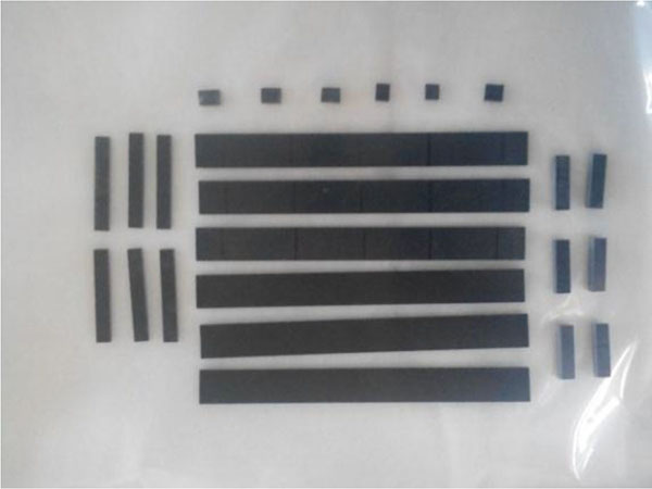 ) are taken to the relative testing. The properties of Epofine resin are shown in (Table 2).
 |
Fig. (2) Laminates after cutting. |
3. TESTING
Generally, two types of tests are carried out, viz., the non-destructive testing (NDT) and the destructive testing (DT). Under the DT, mechanical tests (tensile test, flexural test and inter-laminal shear stress (ILSS)) are carried out. The different mechanical tests with the ASTM standards and the average specimen dimensions are shown in Table (3). At last, the physical tests of the laminate (density, fiber content, resin content and void content tests) are also done.
Table (3) Different mechanical tests with the ASTM standards and the average specimen dimensions.
3.1. NDT
NDT is a wide group of analytical techniques used in science and industry, to evaluate the properties of materials without causing any damage to the specimen. The ultrasonic type is used, and no visual defects are observed. It uses high frequency and short wavelength of mechanical waves (vibrations). The manual type is used. The ultrasonic testing system consists of a transducer, pulser/receiver and display unit. A pulser/receiver produces electrical pulses of high voltage to the transducer. Then, the transducer generates ultrasonic sound energy of high frequency into the material surface in the form of sound waves. If there are discontinuities in the sound path, a fraction of sound energy is reflected from the discontinuities and received by the transducer. In the display unit, the intensity of the transformed electrical signal from the sound wave signal is shown. For the testing, five random points are marked on the laminate. The two probes are used to test the selected points. If the result of the laminate at the selected point is above 90% (‘A’ grade), the test piece is good and ready to use. ‘A’ grade is obtained at all the selected points, which means that the specimen is good.
3.2. DT
The DT tests are carried out using an electromechanical universal testing machine (UTM) to the specimen's failure, in order to understand the specimen's structural behaviour, under the application of loads. A UTM machine, with makes ‘Fuel Instruments and Engineers Pvt. Ltd. (Maharastra), model UTN-20 (maximum capacity 200 kN)’, is used in this study. Generally, these tests are much easier to carry out and provide more information than the NDT. The electromechanical UTM is used to test the tensile test, the flexural test and the ILSS test. The dimensions of the specimen are taken using a digital vernier caliper (brand: Mitutoyo; range 0-300 mm).
3.2.1. Tensile Test
Tensile test is a commonly used material science test, in which the specimen is subjected to a controlled tension until it fails. For the composite materials biaxial tensile testing is used. The test pieces of required dimensions are placed in the jaws of the electromechanical UTM; slowly, the tensile load is applied. The ASTM standard is D3039, the gauge length is 150 mm, and the cross head speed is 2.5 mm\min. During the test, an extensometer of gauge length 25 mm is used, to measure the strain of the laminate. The laminates, before and after the tensile test, are shown in (Fig. 3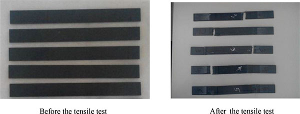 ).
).
 |
Fig. (3) Laminates, before and after the tensile test. |
The tensile testing of five laminates is carried out, and the tensile strength, the tensile modulus and the failure mode are tabulated in Table 4. In Table (4), the specimen failure mode is represented by three-part code letter as per ASTM D3039 standard. The first letter indicates the failure type, the middle letter indicates the failure area, and the last letter indicates the failure location.
Using the stress-strain data, the tensile modulus is calculated. The tensile strength is calculated as
 |
(1) |
Where, W and t are the width and thickness of the specimen, respectively. The average tensile strength and average tensile modulus of the laminate are found to be 654.8 MPa and 54 GPa, respectively.
3.2.2. Flexural Test
A three point flexural test is conducted. In the flexural test, the test pieces of required dimension are placed in the electromechanical UTM roller support, at a distance of span length of roller supports. The ASTM standard is D790, the support spam length is 48 mm (16xt = 16x3 = 48, where t is the thickness), and the cross head speed is 2 mm\min. Fig. (4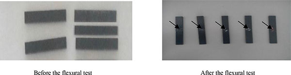 )shows the laminates, before and after the flexural test. In Fig. (4), arrow marks indicate the failure area.
 |
Fig. (4) Laminates, before and after the flexural test. |
The flexural testing of five laminates is carried out, and the flexural strength, the flexural modulus and the failure mode are tabulated in Table 5. In Table 5, ‘C’ means compression and ‘T’ means tension. Using the stress-strain data, the flexural modulus is calculated. The flexural strength is calculated as
 |
(2) |
Where, P is the load, s is the span length, W is the width of the specimen, and t is the thickness of the specimen. The average flexural strength and flexural modulus of the laminate are found to be 704.2 MPa and 60 GPa, respectively.
3.2.3. ILSS Test
ILSS is the source of failure, a unique characteristic of the composite structure. The presence of ILSS in the laminate leads to breaking of the lamination. The ILSS arises due to the various reasons. One is the material property between the layers. The ILSS would tend to shear apart the interface in the corresponding directions.
In this test, the load is applied tangentially on the surface of the laminate; when the load reaches the maximum, the first layer of laminate breaks. The ILSS tests are performed by using a rigid three-point bending fixture in the UTM. The span-to-thickness ratio is 10 mm, which is very short. This tends to high shearing forces and relatively low bending moments in the laminate. The ASTM standard is D2344, support span length is 24 mm (4 x t = 4 x 6 = 24, where t is the thickness), and the cross head speed is 1 mm\min. Fig. (5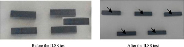 ) shows the laminates, before and after the ILSS test. In (Fig. 5) arrow marks indicate the failure area.
 |
Fig. (5) Laminates before and after the ILSS test. |
The ILSS testing of five laminates is carried out, and the ILSS values are tabulated in Table (6). The ILSS is calculated as
 |
(3) |
Where, P is the load, W is the width of the specimen, and t is the thickness of the specimen. The average ILSS strength is found to be 34.51 MPa.
3.3. Physical Tests of the Laminate
3.3.1. Density of the laminate
The density of the laminate is unknown as we do not know the mass occupied by the volume of the fiber and can be calculated by Archimedes’ principle. Three specimens (10x10, mm2) are taken into the Accurate Sartorius weighing machine. The weight of each specimen is measured in air. Now, the specimens are placed in a crucible with distilled water for 2 minutes to remove the air bubbles. Subsequently, the weight is measured with distilled water. The difference between the two measured values gives the weight loss in water by Archimedes’ principle.

The density of the laminate is calculated as
 |
(4) |
Where, Wa is the weight of the solid laminate in air, Ww is the weight of the laminate in water, and (Wa - Ww) is the weight loss of the laminate in water. Table (7). shows the density test data of the laminate. The average density of the laminate is found to be 1.363 g/cm3.
3.3.2. Fiber Content and Resin Content Tests
Three specimens are chosen to know the amount of fiber and resin in the laminate of size 10 mm x10 mm. First, the weight of the laminate is measured. Subsequently, these are taken into a beaker which is filled with nitric acid (about 50ml). The beakers are placed on the heater surface for 2 to 3 hours, at a temperature 50°C to 60°C. On contact with nitric acid, the resin in the laminate gets dissolved. The fiber gets separated, and the filtration process is carried out. Before the filtration process, the empty crucible is placed in the furnace at a temperature 110°C for 1 hour, to remove the moisture content in the crucible. Then, the weight of each crucible is measured, and the values are noted down. Cleaning is furnished by alternately applying acetone and distilled water for about three times. The separated fiber from the resin is placed into the muffle furnace at about 110°C for an hour. Now, the weight of the crucible with fiber is measured. The difference of the two gives the actual weight of the fiber. Eqs. 5 and 6 define the percentage of the fibre content and the resin content in the laminate, respectively.
 |
(5) |
 |
(6) |
Where, Wa is the weight of the solid laminate in air, Wb is the weight of the empty crucible, Wc weight of the crucible with fiber, and (Wc- Wb) is the weight loss of the fiber content. Table (8). shows the test data of the fiber content and the resin content in the laminate. The average fiber content and the average resin content are found to be 47.61% and 52.39%, respectively.
3.3.3. Void content
The void content is calculated as per eq. 7.
 |
(7) |
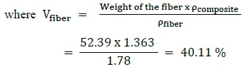 |
(8) |
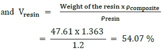 |
(9) |
Therefore, void content = 100 - (40.11 + 54.04) = 5.82%
4. RESULTS AND DISCUSSION
The summary of the test results is shown in Table (9). The requisite average values are compared with the obtained average values, considering various test parameters. From Table (9), it is observed that the obtained average values of the laminate are higher than the requisite average values. Hence, the laminates can be used in many industrial and commercial applications as a composite material.
CONCLUSION
Experiments are carried out to prepare PAN carbon fiber/epoxy resin composites, using the hand-lay-up method. Epofine-1555 is used as the epoxy resin. The mixture of the resin and hardener (equal to the weight of the fiber) is prepared. The resin and hardener are taken in the ratio of 100:27. The different processes, such as cleaning, pre-preg, curing and cutting, are carried out to produce the matrix laminates. The composite matrix laminates are in size 250 mm x 250 mm and 150 mm x 150 mm. The PAN carbon/epoxy laminates are in good condition.
Then, two types of tests, i.e., the non-destructive testing and the destructive testing are carried out. For the non-destructive testing, the ultrasonic type is used, and no visual defects are observed. For the destructive testing, a UTM is used to test the tensile test, the flexural test and the ILSS test, as per the ASTM standard. Subsequently, the physical properties, such as the density test and the fiber content, the resin content and the void content tests of the laminate are carried out.
The experimental results show that the matrix laminates have good mechanical and physical properties. Due to multiple layers, the differences in structure and composition give the desired properties to the laminates [21W. Brostow, and H.E. Lobland, Materials: Introduction and Applications., John Wiley and Sons: New York, 2017.]. The correlation of the above results emphasizes the significance of adequate combination and proper reinforcement in the matrix composite. Hence, the laminates can be used in many industrial and commercial applications, as a composite material.
ETHICS APPROVAL AND CONSENT TO PARTICIPATE
Not applicable.
CONSENT FOR PUBLICATION
Not applicable.
CONFLICT OF INTEREST
The author (editor) declares no conflict of interest, financial or otherwise.
ACKNOWLEDGEMENTS
Declared none.