- Home
- About Journals
-
Information for Authors/ReviewersEditorial Policies
Publication Fee
Publication Cycle - Process Flowchart
Online Manuscript Submission and Tracking System
Publishing Ethics and Rectitude
Authorship
Author Benefits
Reviewer Guidelines
Guest Editor Guidelines
Peer Review Workflow
Quick Track Option
Copyediting Services
Bentham Open Membership
Bentham Open Advisory Board
Archiving Policies
Fabricating and Stating False Information
Post Publication Discussions and Corrections
Editorial Management
Advertise With Us
Funding Agencies
Rate List
Kudos
General FAQs
Special Fee Waivers and Discounts
- Contact
- Help
- About Us
- Search


The Open Cybernetics & Systemics Journal
(Discontinued)
ISSN: 1874-110X ― Volume 12, 2018
A Study on Narrow-band THz (Terahertz) Source with Adjustable Center Frequency Based on Optical Rectification
Ling Zhou1, Xiang-wen Li1, Jiang-ming Kuang1, Shuang Zhang*, 1, 2, Yi-he Liu*, 2
Abstract
The center frequency of the narrow-band THz wave is always unstable with the optical rectification methods. Therefore, the high-phase stable time-delay generator Etalon and the parallel grating pair compressor with the self-adaptive optical path compensation function are designed according to the principle that two lasers in different paths will result in specific relative time delay; with LiNbO3 waveguide sample as the optical rectification crystal, the quasi-multi-cycle narrow-band THz wave generating platform is set up based on the two chirp-delay schemes (one Compressor in the pump branch and another Compressor in the probe branch) Both schemes can generate narrow-band THz waves with adjustable center frequency from 0.25~1.2THz. The bandwidth is 100GHz, with good frequency stability.
Article Information

Identifiers and Pagination:
Year: 2016Volume: 10
First Page: 172
Last Page: 179
Publisher Id: TOCSJ-10-172
DOI: 10.2174/1874110X01610010172
Article History:
Received Date: 31/03/2016Revision Received Date: 18/07/2016
Acceptance Date: 17/08/2016
Electronic publication date: 13/10/2016
Collection year: 2016
open-access license: This is an open access article licensed under the terms of the Creative Commons Attribution-Non-Commercial 4.0 International Public License (CC BY-NC 4.0) (https://creativecommons.org/licenses/by-nc/4.0/legalcode), which permits unrestricted, non-commercial use, distribution and reproduction in any medium, provided the work is properly cited.
* Address correspondence to these authors at the College of Computer Science, Neijiang Normal University, Neijiang, 641000, P.R. China; Tel: +86 832 2343466; Fax: +86 832 2340320; E-mails: zhangshuanghua1@126.com, liu_yihe@163.com.
| Open Peer Review Details | |||
|---|---|---|---|
| Manuscript submitted on 31-03-2016 |
Original Manuscript | A Study on Narrow-band THz (Terahertz) Source with Adjustable Center Frequency Based on Optical Rectification | |
1. INTRODUCTION
The THz wave is between microwave and infrared ray. As the only frequency band is not fully exploited and utilized, it is one of the hot spots in scientific study. Because this technology has important discipline value and wide application prospect in many fields, such as communication, radar, safety inspection imaging, bio-medicine and spectrum analysis, it is honored as one of the ten technologies to change the future world [1M. Kun, and Z.S. Cheng, "Polarization dependent THz generation efficiency by optical rectification in LiNbO3 [A", Proceedings of the SPIE, 2015 ]. THz radiation generation and THz wave-guiding are the two most important techniques in the THz technology [2S.H. Yang, "Hashemi, “7.5% Optical-to-THz conversion efficiency offered by photoconductive emitters with three-dimensional plasmonic contact electrodes", IEEE T. Terahertz Sci. Tech., vol. 4, no. 5, pp. 575-581, 2014.
[http://dx.doi.org/10.1109/TTHZ.2014.2342505] ]. The THz sources and wave-guiding devices are also vital components in the THz system. It is necessary to study THz sources [3S. Ofir, and P. David, "High resolution spectroscopic study in the THz", IEEE Sens. J., vol. 14, no. 2, pp. 547-553, 2014.
[http://dx.doi.org/10.1109/JSEN.2013.2284353] ].There are two kinds of THz radiation sources: one is wideband pulse source; the THz radiation of the source is generally generated by femtosecond laser to motivate different material. Two kinds of generation mechanisms are photoconductive and optical rectification, researching the first and the most common one. Another is the narrow band continuous source; it is gained by spreading microwave source from the low frequency to high frequency, using the electronics method. But it can also be gained by extending low frequency range using optical technology (especially laser technology) [4X. Wang, W. Xiong, W. Sun, and Y. Zhang, "Coaxial waveguide mode reconstruction and analysis with THz digital holography", Opt. Express, vol. 20, no. 7, pp. 7706-7715, 2012.
[http://dx.doi.org/10.1364/OE.20.007706] [PMID: 22453449] ]. Among them, the radiation sources generated based on the electronics methods such as Gunn oscillator, backward wave tube, and so on, are generally small and they have compact structures, and their average powers are between microwatt level and mill-watt level, but their transmitting frequency is low, usually less than 1 THz; the radiation sources generated based on the optics methods, such as gas laser, free electron laser, and so on, can produce THz radiation with a wide frequency range [5G. Yinghui, Y. Lianshan, and P. Wei, "Ultra-broadband THz absorbers based on 4×4 cascaded metal-dielectric pairs", Plasmonics, vol. 9, p. 951, 2014.
[http://dx.doi.org/10.1007/s11468-014-9701-8] ].
The quasi mono-cycle broadband THz source based on optical rectification can obtain high THz pulse energy and wide spectral bandwidth, so it has wide application prospect [6B.Z. Xu, C.Q. Gu, Z. Li, and Z.Y. Niu, "A novel structure for tunable terahertz absorber based on graphene", Opt. Express, vol. 21, no. 20, pp. 23803-23811, 2013.
[http://dx.doi.org/10.1364/OE.21.023803] [PMID: 24104291] ]. But in many applications, the narrow-band THz source with adjustable center frequency is also needed. The source can be used to avoid interference of out-of-band frequency and reduce the use of filter components in THz radar and communication systems.
With the development of research on photoconductive materials, the THz radiation frequency can range from 0.1THz to 30THz, produced by photoconductive antenna [7B. Zhang, Y. Pi, and J. Li, "THz imaging radar with inverse aperture synthesis techniques: system structure, signal processing and experiment results", IEEE Sens. J., 2014.]. At the same time, part of the energy, which is used to launch the THz wave in photoconductive antenna, is coming from the bias field, thus higher gain can be obtained by increasing bias voltage, and the highest average power can reach mill-watt level. So, the photoconductive antenna becomes one of the most widely used THz sources, which have very good performance and potential application value [8Y. Zhang, Y. Feng, B. Zhu, J. Zhao, and T. Jiang, "Graphene based tunable metamaterial absorber and polarization modulation in terahertz frequency", Opt. Express, vol. 22, no. 19, pp. 22743-22752, 2014.
[http://dx.doi.org/10.1364/OE.22.022743] [PMID: 25321743] ]. In this paper, the generation mechanism of narrow-band THZ wave using optical rectification is analyzed based on the Chirp-Delay method.
Since narrowband THz wave’s generation setup usually suffers from instability in the center frequency and difficulty in alignment, on the basis of the principle that different optical path lengths will produce a particular relative delay, a delay generator with high phase stability called Etalon is designed to guarantee frequency stability of the narrowband THz sources. In this paper, a LiNbO3 waveguide slab is selected as an optical rectification crystal, and two Chirp-Delay schemes setups (a compressor in pump arm and another compressor in probe arm) are built.
2. MECHANISM OF OPTICAL RECTIFICATION FENERATING NARROW-BAND THz WAVES
Different from the broadband THz wave generated from optical rectification, the narrow-band THz wave is produced by optical frequency mixing of two linearly chirped broadband laser pulses with specific delay-time in the nonlinear crystal. The superposition of the two chirped pulses with specific delay-time will produce an electromagnetic wave with quasi-sinusoidal laserintensity envelope modulation [9N.C. Chen, T.H. Chang, and C.Y. Yang, "Broadband conversion of TE01 mode for the coaxial gyrotron at low THz", Phys. Plas, vol. 19, 2012.]. Then it is used to stimulate the nonlinear crystal to radiate and generate the narrow-band THz wave. The frequency of the THz wave is determined by the pulse width of the two chirped pulses and their relative delay time. Assuming that the two chirped pulses have the same laser intensity, the first pulsed electric field can be given by:
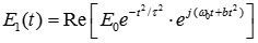 |
(1) |
A Fourier transform limited laser pulse with a pulse width τ0 of 800nm produces the linearly or nonlinear chirp after going through a compressor/stretcher and introducing the phase shift related to the frequency. Then the phase of each spectral component in the laser pulse is changed, so as to change the position of each frequency component in time domain accordingly. At last, a chirped pulse with a wide pulse width (τ1) is formed.
The pulse width (τ1) of the chirped pulse and delay time (Δt) between two chirped pulses is properly controlled to produce a narrow-band THz wave with a specific center frequency. In other words, a specific Compressor and a delay time pulse sequence generator Etalon must be designed.
2.1. Design of Etalon
An ideal Etalon can produce two output pulses with two relative delay time Δt and the same intensity. A simple way to get the specific relative delay time is to divide the incident laser into two parts and separate them in two different optical paths. Based on this idea, an Etalon is designed. It is composed of a partial reflector (38.2% reflection and 61.8% transmission), a completely reflecting mirror and the even air gap between them. The partial reflector is parallel to the completely reflecting mirror and their distance (the thickness of the air gap) will decide the relative delay time produced by Etalon. When a laser beam with a laser intensity of I0 is vertically or approximately vertically directed to the partial reflector, the direct reflective laser intensity is I0×R, and the transmission laser intensity is I0×T. The transmission laser is then transmitted by the completely-reflecting mirror and the partial reflector. Its laser intensity is I0×T2. The laser intensity of the output pulse sequence from Etalon is successively I0 × [ R,T2,T2R,T2R2,T2R3,T2R4,T2R5,T2R6…].
The reflectivity of the first mirror in Etalon is chosen to make the intensities of two beams of output laser have the equal amplitude. That is, R = T2 = (1 - R)2
Then R can be derived as follows:
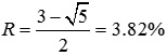 |
(2) |
At this time, the first and the second output pulses’ laser intensities account for the most part (76%). The laser intensity of the third and the remaining output pulses is reduced by a scaling factor of 0.38. According to the stimulation, the remaining pulse sequence has no effect on generating the laser intensity with quasi-sinusoidal envelope modulation.
In order to make the output serial pulses overlap in space, the incident laser should be vertically or approximately vertically directed to Etalon. The relative delay time of each output pulse is Δt = 2h/c.
2.2. Design of Compressor
In order to make the output serial pulses from Etalon able to overlap, the incident ultra-short laser pulse width shall go through a Compressor (pulse stretcher) to introduce a phase-shift phase related to the frequency and to adjust the position of each frequency component in the time domain. Thus the chirped pulse with a wide pulse width (τ1) is formed.
Assuming that an initial incident pulse goes through an optical system and the initial incident pulse E 0(t) is given by:
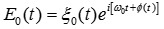 |
(3) |
In the equation, ξ (t) is the slowly varying envelope, ω0 the center frequency, and Φ(t) is the phase shift of the Fourier transform limited pulse. When Φ(t)=0, the Gaussian pulse is:
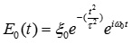 |
(4) |
In the equation, τ0FWHM refers to FWHM of the pulse.
After Fourier Transform of the equation is performed, the equation of the incident pulse in frequency domain can be derived as follows:
 |
(5) |
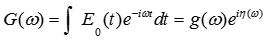
In the equation, g (ω) and η (ω) are spectrum amplitude and phase respectively. Therefore, the output pulse of the incident pulse through the optical system can be expressed as:
 |
(6) |
In the equation, s[ω] refers to the complex transfer function of the optical system. It will directly affect the phase of the output pulse. This optical system can be a Compressor which is composed of dispersive media, chirped mirror pair, three prisms pair or parallel grating pair. The biggest advantage of the parallel grating pair Compressor is that it can provide bigger group velocity dispersion (GVD), compared with glasses, prisms or chirped mirrors. For example, when a laser with a central wavelength of 800nm and a pulse width of 100fs is directed into the 830.8 L/mm grating pair in an incident angle of 14.8o, and the distance L0 between the grating pair is 7~72cm, 3~30ps pulse width of the output chirped pulse can be achieved . The parallel grating pair compressor can be used to build a platform generating narrow-band THz wave based on optical rectification.
The narrow-band THz source with adjustable center frequency is based on two Chirp-Delay optical path schemes. That is, 54μm-thick LiNbO3 crystal waveguide sample is used as the optical rectification crystal, and platforms generating quasi multi-cycle narrow-band THz wave are set up respectively in the Pump branch and the Probe branch of the Compressor.
2.3. Experiment to Generate Narrow-band THz in Pump Branch of the Compressor
In the platform, the experimental optical path generating the narrow-band THz wave in Pump branch of the Compressor reduces the spot diameter of the 800nm incident laser with a pulse width of 100fs and a power of 0.6w to 5mm through a double-lens system. Then the incident laser is divided into the Pump branch and the Probe branch by a beam splitter.
In the Pump branch, the pump laser goes through the Compressor. The chirped pulse with extended pulse width is formed because of group velocity dispersion; it is approximately vertically directed to Etalon and a chirped pulse sequence with a delay time of about 1ps is generated after reflection, so as to form the pump wave intensity with quasi-sinusoidal modulation. Then it goes through a chopper and is focused on a LiNbO3 waveguide sample with a lens, thus the quasi multi-cycle narrow-band THz wave is generated by optical rectification.
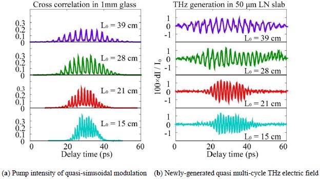 |
Fig. (1) Experiment result. |
In the Probe branch, the probe laser goes through the optical path controllable delay platform to be directed to BBO, thus a 400nm second harmonics is formed to detect the THz wave generated by the pumping laser in LiNbO3. The concrete method is detailed as follows: First, the first optical grating G1 in installed on a large breadboard to make the laser with a center wave length of 800nm in the first-order diffracting beam parallel to the through-hole of the board; next, the second optical grating G2 and the heightened mirror are installed on a small L-shaped breadboard. Then the small board is installed on the large breadboard. The large board is fixed to the experiment table. A slideway is designed to make the small board slide on the large board along the through-hole direction. The incident laser is paralleled to the through-hole and directed to the mirror (M1) on the small board. Then it is reflected by the mirror M2 and returns parallel. And it is reflected again to the first optical grating G1 and then it is diffracted to the second optical grating G2, next, it is diffracted to the heightened mirror. Then it is reflected by the heightened mirror to G2 and G1, thus the chirped pulse is emitted. Before entering Compressor, by sliding the small bread board, the increase (or reduction) of the optical path by M1 and M2 can be compensated by the grating in the Compressor by reducing (or increasing) the optical path between G1 and G2. In this way, the general optical path is kept constant. Therefore, moving the platform in the experiment can change dispersion measure of the Compressor to adjust the frequency generating THz. The self-adaptive optical path compensation facilitates the experiment and test by directly detecting the laser without re-calculating the optical path of the probe laser. The pump intensity is tested with a 1mm glass sample. The pump laser and the probe laser are focused on the same spot of the glass sample. The pump intensity is then tested according to Kerr effect (Fig. 1a ). The test of THz electric field generated in optical rectification is made with a 54μm-thick LiNbO3 waveguide to make the probe intensity deviate from the pump intensity. The time domain wave form of the quasi multi-cycle THz electric field is tested according to Pockets effect (Fig. 1b). When the distance L0 between the parallel gratings is 15cm, 21cm, 28cm and 39cm, the chirped pulse group velocity dispersion generated in this way also grows in arrangement. Similarly, the pulse width of the pump intensity generating quasi-sinusoidal modulation also grows. Because the delay time caused by Etalon is kept constant, the periodic numbers in FWHM of the pump intensity of quasi-sinusoidal modulation and the time domain waveform generating THz are also constant. The Fourier transform of the time domain waveform in the THz electric field in Fig. (1b) is performed and the amplitude-frequency curve of the THz electric field is generated. As can be seen in Fig. (2
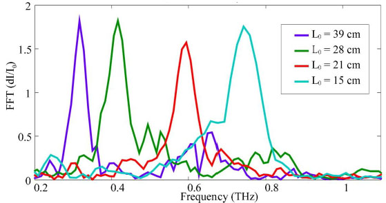 ), the different distance L0 between the parallel gratings generates THz waves with 0.75THz, 0.59THz, 0.42THz and 0.315THz respectively. The bandwidth is about 100GHz, with good frequency stability.
 |
Fig. (2) Amplitude-frequency curve of the newly-generated narrow-band THz wave. |
2.4. Experiment to Generate Narrow-band THz in Probe Branch of the Compressor
In the platform experiment optical path to generate narrow-band THz in Probe branch of the Compressor, the Compressor is in the Probe branch. The chirped pulse should be shot on Etalon to generate narrow-band THz. The Compressor in the laser is adjusted to output positive chirped pulse. Then the pulse is divided into Pump branch and Probe branch by a beam splitter.
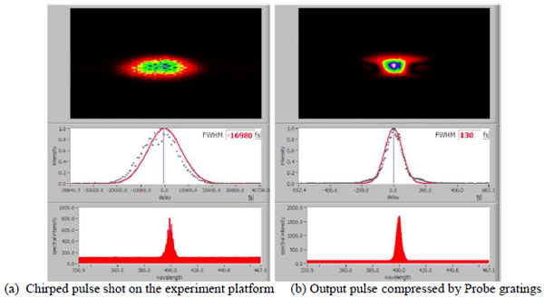 |
Fig. (3) Laser pulse measured with SHG-FROG. |
In Pump branch, the chirped pulse pumping laser is shot on Etalon approximately vertically and generates a chirped pulse sequence with a delay time of about 1ps after reflection. The pump intensity of quasi-sinusoidal modulate is then formed. Going through the chopper, it is focused on a LiNbO3 waveguide sample with a lens to form quasi multi-cycle narrow-band THz by optical rectification. In Probe branch, the probe laser first goes through the self-adaptive Compressor compensating the optical path to provide negative dispersion and change the positive chirped pulse into the Fourier transform limit pulse. Then it shots on BBO through the delay platform to form 400nm second harmonic so as to detect the THz generated by the pumping laser in LiNbO3.
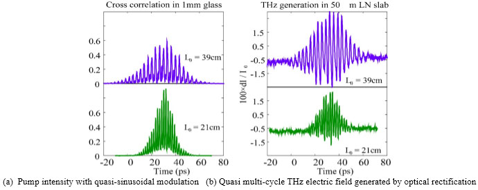 |
Fig. (4) Experiment result. |
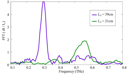 |
Fig. (5) Amplitude-frequency curve of the newly-generated narrow-band THz wave. |
In the experiment platform of the Compressor in Probe branch, the testing principle of the pump intensity and the THz electric field is the same as that of the Compressor in Pump branch. The only difference is that the Compressor in the laser and the Compressor in Probe branch must be adjusted each time before the test. The purpose is to make the positive dispersion measures offset and the negative one so as to form the detecting pulse close to Fourier transform limit. As is shown in Fig. (3 ), the pulse width of the chirped laser pulse is measured with the frequency the second harmonic and the Frequency Resolved Optical Gating “SHG-FROG”, and it is 16.98ps. When the distance L0 between the parallel grating pair in the Probe branch and it is adjusted to about 21cm, the pulse width of 130fs is obtained, which is close to the Fourier transform limit.
Because the testing is comparatively complex, two data sets are tested. When the incident chirped pulse is 17ps and 34.6ps wide, the corresponding distances L0 between the grating pair are 21cm and 39cm respectively. The pump wave intensity with the quasi-sinusoidal modulation and the THz electric field are shown in Fig. (4 ). Fourier transform of the THz electric field in Fig. (4b) is carried out to generate the amplitude-frequency curve of the narrow-band THz electric filed. Fig. (5
 ) shows that their center frequencies are 0.58THz and 0.31THz, respectively.
2.5. Comparison of Two Chirp-delay Experiment Schemes
By comparing the two Chirp-Delay experiment schemes, it can be seen that the optical path scheme with the Compressor in Pump branch is the same as that with the Compressor in Probe branch. Both can utilize the optical rectification effect of the LiNbO3 waveguide sample to effectively produce narrow-band THz with adjustable center frequency. In the experiment result, the frequency used to generate the THz wave is identical to the frequency in the theoretical prediction.
For the scheme of the Compressor in Pump branch, its greatest advantage is that it easy to adjust the optical path and carry out experiment and test. But it may result in energy loss to some extent when the pumping laser goes through the Compressor. Besides, if the ultra-short laser with higher power can reach the narrow-band THz wave generating experiment platform after a long transmission distance, it will cause great air nonlinear effect and distort the pump intensity with quasi sinusoidal modulation. Thus the generation of the narrow-band THz will be affected. In the scheme with the Compressor in Probe branch, the incident laser is chirped pulse. There is no Compressor in Pump branch and higher pump power can be obtained. The chirped pulse has a wide pulse width. It will not cause great air nonlinear effect. However, the Compressor in the optical cavity needs adjusting to get the chirped pulse and it will also bring more difficulty to optical path adjustment and may affect other experiments using the same laser together.
CONCLUSION
In this study, the design of Etalon and Compressor is proposed, and the experiment platform used to generate the narrow-band THz wave is set up; and intensive study is conducted on the narrow-band (quasi multi-cycle) THz source based on nonlinear optical rectification. A delay-time generator Etalon is designed. The test shows it has good phase stability and can generate stable relative delay-time pulse sequence. The parallel grating pair Compressor with self-adaptive optical path compensation function is designed to facilitate the generation of narrow-band THz and its test experiment. The LiNbO3 waveguide sample is used as the optical rectification crystal. A quasi multi-cycle narrow-band THz wave generating platform based on two Chirp-Delay schemes (one compressor in the pump branch and another compressor in the probe branch) is set up. The experiment shows that both schemes can effectively generate narrow-band THz with adjustable center frequency. The center frequency can be adjusted from 0.25 THz to 1.2THz. The bandwidth is about 100GHz, with good frequency stability.
CONFLICT OF INTEREST
The authors confirm that this article content has no conflict of interest.
ACKNOWLEDGEMENTS
The work presented in this paper is supported by The Key Fund Project of Sichuan Provincial Department of Education under Grant13ZA0003, Grant 14ZB0360, Grant 14ZB0363, Grant 14ZB0352; The Sichuan Province Department of Science and Technology under Grant 2015JY0119,the Key Fund Project of Leshan Science and Technology Bureau (15ZDYJ0177). The Engineering and Technical College of Chengdu University of Technology under Grants (C122015005,C122015002,C122016002,C122016004, C122016030).
REFERENCES
| [1] | M. Kun, and Z.S. Cheng, "Polarization dependent THz generation efficiency by optical rectification in LiNbO3 [A", Proceedings of the SPIE, 2015 |
| [2] | S.H. Yang, "Hashemi, “7.5% Optical-to-THz conversion efficiency offered by photoconductive emitters with three-dimensional plasmonic contact electrodes", IEEE T. Terahertz Sci. Tech., vol. 4, no. 5, pp. 575-581, 2014. [http://dx.doi.org/10.1109/TTHZ.2014.2342505] |
| [3] | S. Ofir, and P. David, "High resolution spectroscopic study in the THz", IEEE Sens. J., vol. 14, no. 2, pp. 547-553, 2014. [http://dx.doi.org/10.1109/JSEN.2013.2284353] |
| [4] | X. Wang, W. Xiong, W. Sun, and Y. Zhang, "Coaxial waveguide mode reconstruction and analysis with THz digital holography", Opt. Express, vol. 20, no. 7, pp. 7706-7715, 2012. [http://dx.doi.org/10.1364/OE.20.007706] [PMID: 22453449] |
| [5] | G. Yinghui, Y. Lianshan, and P. Wei, "Ultra-broadband THz absorbers based on 4×4 cascaded metal-dielectric pairs", Plasmonics, vol. 9, p. 951, 2014. [http://dx.doi.org/10.1007/s11468-014-9701-8] |
| [6] | B.Z. Xu, C.Q. Gu, Z. Li, and Z.Y. Niu, "A novel structure for tunable terahertz absorber based on graphene", Opt. Express, vol. 21, no. 20, pp. 23803-23811, 2013. [http://dx.doi.org/10.1364/OE.21.023803] [PMID: 24104291] |
| [7] | B. Zhang, Y. Pi, and J. Li, "THz imaging radar with inverse aperture synthesis techniques: system structure, signal processing and experiment results", IEEE Sens. J., 2014. |
| [8] | Y. Zhang, Y. Feng, B. Zhu, J. Zhao, and T. Jiang, "Graphene based tunable metamaterial absorber and polarization modulation in terahertz frequency", Opt. Express, vol. 22, no. 19, pp. 22743-22752, 2014. [http://dx.doi.org/10.1364/OE.22.022743] [PMID: 25321743] |
| [9] | N.C. Chen, T.H. Chang, and C.Y. Yang, "Broadband conversion of TE01 mode for the coaxial gyrotron at low THz", Phys. Plas, vol. 19, 2012. |