- Home
- About Journals
-
Information for Authors/ReviewersEditorial Policies
Publication Fee
Publication Cycle - Process Flowchart
Online Manuscript Submission and Tracking System
Publishing Ethics and Rectitude
Authorship
Author Benefits
Reviewer Guidelines
Guest Editor Guidelines
Peer Review Workflow
Quick Track Option
Copyediting Services
Bentham Open Membership
Bentham Open Advisory Board
Archiving Policies
Fabricating and Stating False Information
Post Publication Discussions and Corrections
Editorial Management
Advertise With Us
Funding Agencies
Rate List
Kudos
General FAQs
Special Fee Waivers and Discounts
- Contact
- Help
- About Us
- Search


The Open Electrical & Electronic Engineering Journal
(Discontinued)
ISSN: 1874-1290 ― Volume 13, 2019
Research on Calibration Method for Tractor Automatic Navigation Control System
Qun Sun1, *, Shaomin Teng2, Yongqi Du2, Ze Kang3, Chengqiang Yin1, Linlin Chen1
Abstract
A lower computer control system of tractor automatic navigation based on double-antennas Beidou satellite is developed, including the controller unit, bipolar output unit, RS232 bus communication unit, a switch reset unit and the power conversion unit. To obtain a continuous voltage output, the calibration method of lower control system using least square method to fit calibration curve has been studied. The lower computer control system receives navigation angel and navigation angel offset instruction provided by the host computer through RS232 bus communication unit. Continuous voltage from -10V to +10V is output through the bipolar output unit to adjust hydraulic valves to control the tractor steering after these are processed by the lower computer.
Article Information

Identifiers and Pagination:
Year: 2016Volume: 10
First Page: 129
Last Page: 140
Publisher Id: TOEEJ-10-129
DOI: 10.2174/1874129001610010129
Article History:
Received Date: 29/02/2016Revision Received Date: 06/07/2016
Acceptance Date: 15/07/2016
Electronic publication date: 15/11/2016
Collection year: 2016
open-access license: This is an open access article licensed under the terms of the Creative Commons Attribution-Non-Commercial 4.0 International Public License (CC BY-NC 4.0) (https://creativecommons.org/licenses/by-nc/4.0/legalcode), which permits unrestricted, non-commercial use, distribution and reproduction in any medium, provided the work is properly cited.
* Address correspondence to this author at the School of Mechanical and Automotive Engineering, Liaocheng University, No.1 Road Hunan Road, Liaocheng, Shandong, China; Tel: 86-0635-8239988; E-mail:sunxiaoqun97@163.com
| Open Peer Review Details | |||
|---|---|---|---|
| Manuscript submitted on 29-02-2016 |
Original Manuscript | Research on Calibration Method for Tractor Automatic Navigation Control System | |
1. INTRODUCTION
Automatic navigation technology of agricultural machinery is one of the important support technologies of modern agricultural equipment. Its application in precision agriculture is regarded as one of the main issues noteworthy for efficiency improvement [1J.F. Reid, Q. Zhang, and N. Noguchi, "Agricultural automatic guidance research in North America", Comput. Electron. Agric., vol. 25, no. 12, pp. 155-167, 2000.
[http://dx.doi.org/10.1016/S0168-1699(99)00061-7] , 2Q. Zhang, and H.C. Qiu, "A dynamic path search algorithm for tractor automatic navigation", Trans. ASAE, vol. 47, no. 2, pp. 639-646, 2004.
[http://dx.doi.org/10.13031/2013.16027] ]. Agricultural machinery automatic navigation technology has important significance in theoretical research and practical applications, because it not only can effectively reduce the driver's labor intensity but also improve the quality of farmland homework. GPS positioning technique in tractor has been widely used in automatic navigation system [3T. Bell, "Automatic tractor guidance using carrier-phase differential GPS", Comput. Electron. Agric., vol. 25, no. 12, pp. 53-66, 2000.
[http://dx.doi.org/10.1016/S0168-1699(99)00055-1] ], driven-by-wire tractors, linked to GPS, and receiving precise mapping data have already led to significant increases in productivity.
According to a recent survey, major studies are focused on different control methodologies [4A. Lu, Z. Song, and E. Mao, "Optimized control method for tractor automatic steering", In: Transactions of the CSAE, 2006, pp. 116-119.-6E. Kayacan, E. Kayacan, and H. Ramon, "Nonlinear modeling and identification of an autonomous tractor-trailer system", Comput. Electron. Agric., vol. 106, pp. 1-10, 2014.
[http://dx.doi.org/10.1016/j.compag.2014.05.002] ], path tracking methods [7J. Backman, T. Oksanen, and A. Visala, "Navigation system for agricultural machines: Nonlinear model predictive path tracking", Comput. Electron. Agric., vol. 82, pp. 32-43, 2012.
[http://dx.doi.org/10.1016/j.compag.2011.12.009] ], ISO 1173 network [8J. Backman, T. Oksanen, and A. Visala, "Applicability of the ISO 11783 network in a distributed combined guidance system for agricultural machines", Biosystems Eng., vol. 114, pp. 306-317, 2013.
[http://dx.doi.org/10.1016/j.biosystemseng.2012.12.017] , 9K. Motobayashi, K. Nishiwaki, Y. Hamada, and R. Okuno, "Standardized control and communication data network for a small range agricultural machinery", IFAC Proceedings Volumes, vol. 46, no. 18, pp. 115-120, .] and vision navigation approaches [10M.R. Blas, and M. Blanke, "Stereo vision with texture learning for fault-tolerant automatic baling", Comput. Electron. Agric., vol. 75, pp. 159-168, 2011.
[http://dx.doi.org/10.1016/j.compag.2010.10.012] ]. The crew of autonomous agricultural vehicles [11G. Stavros, "Vougioukas. A distributed control framework for motion coordination of teams of autonomous agricultural vehicles", Biosyst. Eng., vol. 113, pp. 284-297, 2012.
[http://dx.doi.org/10.1016/j.biosystemseng.2012.08.013] ] and the situation awareness of drivers [12B. Bashiri, and D.D. Mann, "Automation and the situation awareness of drivers in agricultural semi-autonomous vehicles", Biosyst. Eng., vol. 124, pp. 8-15, 2014.
[http://dx.doi.org/10.1016/j.biosystemseng.2014.06.002] ] are also studied. The majority of reports used GPS or DGPS+ steering angle sensor as the way of feedback [13S. Gan-Mor, R.L. Clark, and B.L. Upchurch, "Implement lateral position accuracy under RTK-GPS tractor guidance", Comput. Electron. Agric., vol. 59, no. 1, pp. 31-38, 2007.-15G. Bayar, M. Bergerman, and A.B. Koku, "Localization and control of an autonomous orchard vehicle", Comput. Electron. Agric., vol. 115, pp. 118-128, 2015.
[http://dx.doi.org/10.1016/j.compag.2015.05.015] ], which is needed to make improvements in the tractor front wheel steering, or used step motor or servo motor to improve steering system, which can easily control but lose the control precision [16H. Mousazadeh, "A technical review on navigation systems of agricultural autonomous off-road vehicles", Hossein Mousazadeh, vol. 50, pp. 211-232, 2013., 17Z. Liu, "Autonomous navigation system for agricultural tractor based on self-adapted fuzzy control", Trans. Chin. Soc. Agric. Mach., vol. 41, no. 11, pp. 148-152, 2010.
[http://dx.doi.org/10.3969/j.issn.1000-1298] ].
In fact, the performance of the lower machine has important influence on the automatic navigation. A lower machine control system applicable to the hydraulic steering tractor automatic navigation is designed and its calibration method is studied in this article. In the system, double antenna system based on Beidou navigation system is adopted, by which the navigation offset and deflection angle could be obtained directly, and it can avoid using of angle sensor.
2. NAVIGATION SYSTEM STRUCTURE
The whole control structure of tractor automatic navigation system is shown in Fig. (1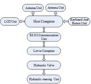 ), which consists of PC, LCD display unit, keyboard and button unit, two Beidou navigation antenna units, RS232 bus communication unit, slave machine, hydraulic unit and hydraulic steering unit.
 |
Fig. (1) The whole control structure. |
3. THE DESIGN OF LOWER MACHINE CONTROL SYSTEM
3.1. Control System Structure
Lower machine control system consists of a freescale MC9S12XS128 single-chip microcomputer controller, RS23 bus communication unit, power conversion unit, overload signal input unit, switch, reset unit, relay output alarm unit, and -10V-+10V bipolar output unit. The control system structure is shown in Fig. (2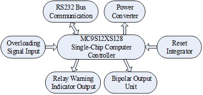 ).
).
 |
Fig. (2) Lower machine control system structure. |
3.2. Control and Measurement Requirements
The control and measurement requirements for lower control system are listed as the following:
- Power supply requirements: 12V DC input (supplied by tractor itself), 3-way 24V DC output (one for the electromagnet proportional hydraulic valve power supply, one for alarm light, one reserved for external power unit), 5V DC power supply for chips in lower computer.
- Communication interface: RS232 bus communication.
- Input signal: overload signal input with 4-20mA current.
- Output signal: the alarm light voltage is 5V and the voltage of electromagnet proportional hydraulic valve is ranged from -10V to +10V.
3.3. Hardware Design of Control System
The hardware of the system includes the following parts:
- Source transformation unit: selecting voltage stabilization module SDW50-12S24 to convert 12V DC into 24V DC, selecting voltage stabilization module SDW50-12S5 to convert 12V DC into 5V DC.
- RS232 bus communication unit: selecting chip MAX232 to convert MCU full-duplex level into RS232 bus communication level.
- Overload signal input unit: selecting module ISO-A4-P1-O4 to transfer the input of 4-20mA standard signal into 5V isolated signal.
- The alarm output unit: selecting the relay SRS-5VDC-SL module as the alarm light of control signal.
- -10V - +10V bipolar output unit: selecting DAC0832 and WD12-5D15B1 to provide standard external voltage of +15V and -15V, while choosing AD581 to provide 10V reference voltage to DAC0832.
The circuit schematic diagram is shown in Fig. (3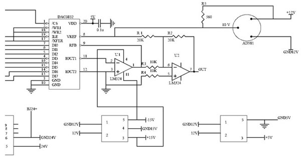 ).
).
 |
Fig. (3) The hardware circuit diagram. |
4. THE CALCULATION METHOD OF CONTROL SYSTEM
4.1. The Transferred Calculation between Current and Voltage of Overload Signal Input Unit
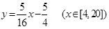
External overload signal input is a standard 4-20mA current signal, which is corresponding to the solenoid valve of 0-3000PSI. Setting the input current as x-coordinate and the pressure value as y-coordinate, equation is established as follows.
 |
(1) |
The curve of I-PSI is shown as Fig. (4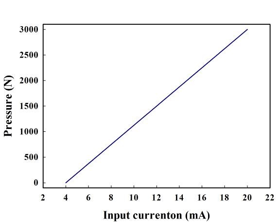 ).
).
 |
Fig. (4) The curve of I-PSI. |
The module ISO-A4-P1-O4 transfers the 4-20mA standard input signal into 5V isolated signal. Setting the input current as x-coordinate and the conversion voltage as y-coordinate, the equation can be established as Eq. (2).
 |
(2) |
The curve of I-U is shown in Fig. (5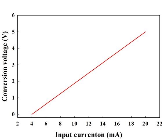 ).
).
 |
Fig. (5) The curve of I-U. |
In a similar way, setting the conversion voltage as x-coordinate and the pressure value as y-coordinate, the curve of U-PSI is shown in Fig. (6 ).
).
 |
Fig. (6) The curve of U-PSI. |
4.2. The Calculation Method of -10v-+10v Bipolar Output Unit
A self-made equipment is used as the demarcating source with output current of 4-20mA.
1. Theoretical curve
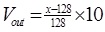
The resolution ratio of DAC0832 is 8-bit, so the output voltage is as follows.
 |
(3) |
As is shown in Eq.(3), the value of x range from 0 to 255.
The dead-band voltage of electromagnet proportional hydraulic has a changing range from -0.8V to 0.8V, which means that the output pressure of magnetic value is 0 when the input voltage is ±0.8V.
Theoretically, the output voltage ranging from -10V to 10V is corresponding to the pressure ranging from 0 to 3000PSI.
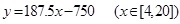
So the theoretical equation is:
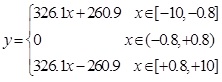 |
(4) |
The theoretical curve is shown in Fig. (7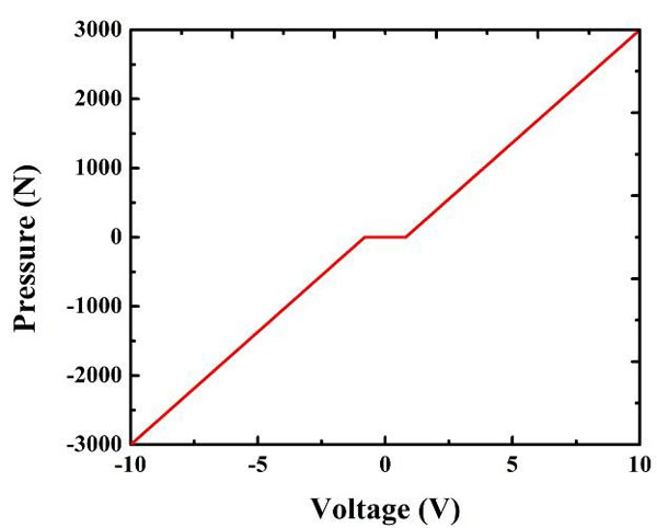 ).
).
2. Assuming x=0, 1, 2,…, n,…, 255, where n is an integer and its range is from 0 to 255. The output delay is 2s, setting the controller to output continually. The calculation data is recorded by Fluke multimeter. Partial data is listed in Table 1 and the curves are shown in Fig. (8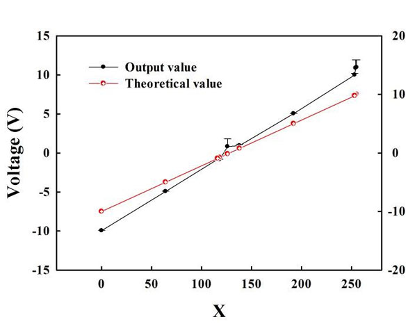 ).
).
 |
Fig. (7) Theoretical curve. |
According to Table 1, the relationship between x and the output value is as follows: [126,253]→[0.8,10]V;[116,0]→[-0.8,-10]V.
In order to achieve the bipolar output, x is divided into 100 equal parts. The equation is given by:
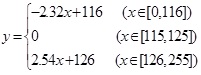 |
(5) |
 |
Fig. (8) Experimental data and error. |
The calculation curve is shown in Fig. (9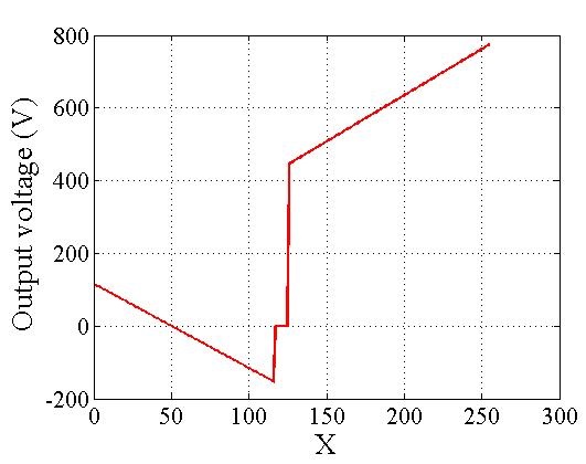 ).
).
 |
Fig. (9) Calculation curve. |
4.3. Least Square Method Fitting
Extracting the data from Table 1 and the new data is listed in Table 2.
Fitting the value of output voltage with the Least Square Method (LSM) [18P. Bochev, and M. Gerritsma, "A spectral mimetic least-squares method", Comput. Math. Appl., vol. 68, no. 11, pp. 1480-1502, 2014.
[http://dx.doi.org/10.1016/j.camwa.2014.09.014] ], the continuous output voltage can be obtained. Specific process is explained in literatures [19M. Gerritsma, and P. Bochev, "A spectral mimetic least-squares method for the Stokes equations with no-slip boundary condition", Comput. Math. Appl., vol. 71, no. 11, pp. 2285-2300, 2016.
[http://dx.doi.org/10.1016/j.camwa.2016.01.033] , 20J.F. Wang, F.X. Sun, and Y.M. Cheng, "Error estimates for the interpolating moving least-squares method", Appl. Math. Comput., vol. 245, pp. 321-342, 2014.
[http://dx.doi.org/10.1016/j.amc.2014.07.072] ].
Through preliminarily tracing the points, it can be seen that the function obeys linear relationship. Assuming the function is:
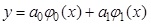 |
(6) |
Among the above, y is the fitting function, a0 and a1 are respectively the constant coefficient of 0-order and 1-order function,
 are respectively the 0-order and 1-order basis function.
Because of the linear relationship between xi and yi, then,
 , which means that the fitting results are only with 0-order basis function and 1-order basis function. According to the principle of least square method, the equation of the question is as follows:
 |
(7) |
Then, the coefficient of the equation is:
 |
(8) |
Among the above, (φj, φk) is the value of the matrix in row k of line j, φj (xi) is the value of jth-order basis function when the independent variable is xi . And φk (xi) is the value of kth-order basis function when the independent variable is xi. (φj, f) is the corresponding fitting value of jth-order basis function, and yi is the fitting value when the independent variable is xi.
The coefficients in the calculating function can be expressed as:
 |
Returning these into the equation, the equation can be set as:
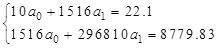 |
(9) |
Therefore, a0 and a1 could be obtained:
a0=-10.078, a1=-0.811.
The fitting curve by using lower square method is shown in Fig. (10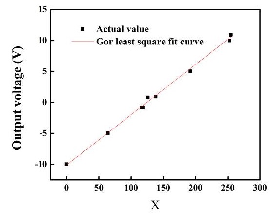 ).
).
5. ANALYSIS OF EXPERIMENTS
5.1. Test Site and Equipment
Experiments were performed in the Jiusan farm of Qiqihar city, north east of China. The developed lower machine controller was installed in a modified Oriental Red X-804 tractor, and the tractor technical parameters are as shown in Table 3. The navigation system adopts Beidou satellite base station CORS series and NETS9 receiver produced by China Guangzhou South Satellite Navigation Co., Ltd.
 |
Fig. (10) Fitting curve with the least square method. |
The photo of developed controller is as shown in Fig. (11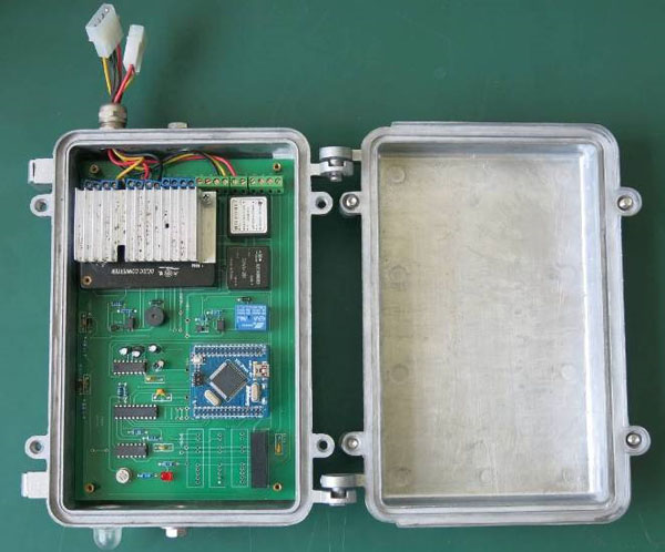 ). The device installed on a tractor is shown in Fig. (12
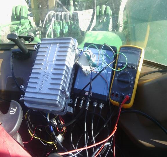 ).
).
 |
Fig. (11) The developed controller. |
 |
Fig. (12) The controller used in the tractor automatic navigation. |
5.2. Linear Tracking Experiments
When the tractor speed is 0.5m/s and 1m/s respectively, the target linear path is 50m and tracking is as shown in Fig. (13 ). The solid lines represent the target paths and the dotted lines are the actual tractor tracks.
 |
Fig. (13) The liner tracking paths of a tracker when the speeds are 0.5m/s and 1m/s. |
The experimental data indicate that as the tractor speed is 0.5m/s, the average deviation is 0.0968m, and the standard deviation is 0.0603m. When the tractor speed is 1m/s, the average deviation is 0.1443m, and the standard deviation 0.1143m. During the test, by adjusting the control parameters of the algorithm, and choosing the best combination of parameters, lateral deviation was set to the relative minimum, with maximum accuracy. The lateral deviation is affected by the tractor driving speed influence, during low speed the lateral deviation is small with high precision, whilst during high speed the lateral deviation increases and the accuracy is reduced.
CONCLUSION
With the tractor automatic navigation as the research objective, a lower machine controller has been developed based on single chip computer, which utilized least square method to achieve voltage calibration of the lower machine controller. Sequential output of -10V-+10V could be achieved and bipolar electromagnetic hydraulic values could be controlled, which could control tractor fluid-link steering.
The experimental results indicate that the designed controller can meet the requirements of tractor steering tracking control, the tractor speed is 0.5m/s, the average deviation is 0.0968m, and the standard deviation is 0.0603m. When the tractor speed is 1m/s, the average deviation is 0.1443 m, the standard deviation 0.1143m. It has good stability and accuracy, which lays the foundation for the lateral deviation control of the tractor. The next step will focus on research, and tests of tractor field operations.
CONFLICT OF INTEREST
The authors confirm that this article content has no conflict of interest.
ACKNOWLEDGEMENTS
This project is founded by Shandong Province Special Funding to Upgrade Technology Research of Large Scientific Instruments (ID: 2013SJGZ26) and A Project of Liaocheng City Science and Technology Development Plan (ID: 2013GHZ07).
REFERENCES
| [1] | J.F. Reid, Q. Zhang, and N. Noguchi, "Agricultural automatic guidance research in North America", Comput. Electron. Agric., vol. 25, no. 12, pp. 155-167, 2000. [http://dx.doi.org/10.1016/S0168-1699(99)00061-7] |
| [2] | Q. Zhang, and H.C. Qiu, "A dynamic path search algorithm for tractor automatic navigation", Trans. ASAE, vol. 47, no. 2, pp. 639-646, 2004. [http://dx.doi.org/10.13031/2013.16027] |
| [3] | T. Bell, "Automatic tractor guidance using carrier-phase differential GPS", Comput. Electron. Agric., vol. 25, no. 12, pp. 53-66, 2000. [http://dx.doi.org/10.1016/S0168-1699(99)00055-1] |
| [4] | A. Lu, Z. Song, and E. Mao, "Optimized control method for tractor automatic steering", In: Transactions of the CSAE, 2006, pp. 116-119. |
| [5] | "Moving horizon estimation and nonlinear model predictive control for autonomous agricultural vehicles", Comput. Electron. Agric., vol. 98, pp. 25-33, 2013. [http://dx.doi.org/10.1016/j.compag.2013.06.009] |
| [6] | E. Kayacan, E. Kayacan, and H. Ramon, "Nonlinear modeling and identification of an autonomous tractor-trailer system", Comput. Electron. Agric., vol. 106, pp. 1-10, 2014. [http://dx.doi.org/10.1016/j.compag.2014.05.002] |
| [7] | J. Backman, T. Oksanen, and A. Visala, "Navigation system for agricultural machines: Nonlinear model predictive path tracking", Comput. Electron. Agric., vol. 82, pp. 32-43, 2012. [http://dx.doi.org/10.1016/j.compag.2011.12.009] |
| [8] | J. Backman, T. Oksanen, and A. Visala, "Applicability of the ISO 11783 network in a distributed combined guidance system for agricultural machines", Biosystems Eng., vol. 114, pp. 306-317, 2013. [http://dx.doi.org/10.1016/j.biosystemseng.2012.12.017] |
| [9] | K. Motobayashi, K. Nishiwaki, Y. Hamada, and R. Okuno, "Standardized control and communication data network for a small range agricultural machinery", IFAC Proceedings Volumes, vol. 46, no. 18, pp. 115-120, . |
| [10] | M.R. Blas, and M. Blanke, "Stereo vision with texture learning for fault-tolerant automatic baling", Comput. Electron. Agric., vol. 75, pp. 159-168, 2011. [http://dx.doi.org/10.1016/j.compag.2010.10.012] |
| [11] | G. Stavros, "Vougioukas. A distributed control framework for motion coordination of teams of autonomous agricultural vehicles", Biosyst. Eng., vol. 113, pp. 284-297, 2012. [http://dx.doi.org/10.1016/j.biosystemseng.2012.08.013] |
| [12] | B. Bashiri, and D.D. Mann, "Automation and the situation awareness of drivers in agricultural semi-autonomous vehicles", Biosyst. Eng., vol. 124, pp. 8-15, 2014. [http://dx.doi.org/10.1016/j.biosystemseng.2014.06.002] |
| [13] | S. Gan-Mor, R.L. Clark, and B.L. Upchurch, "Implement lateral position accuracy under RTK-GPS tractor guidance", Comput. Electron. Agric., vol. 59, no. 1, pp. 31-38, 2007. |
| [14] | Y. Nagasaka, N. Umeda, and Y. Kanetai, "Autonomous guidance for rice transplanting using global positioning and gyroscopes", Comput. Electron. Agric., no. 43, pp. 223-234, 2004. [http://dx.doi.org/10.1016/j.compag.2004.01.005] |
| [15] | G. Bayar, M. Bergerman, and A.B. Koku, "Localization and control of an autonomous orchard vehicle", Comput. Electron. Agric., vol. 115, pp. 118-128, 2015. [http://dx.doi.org/10.1016/j.compag.2015.05.015] |
| [16] | H. Mousazadeh, "A technical review on navigation systems of agricultural autonomous off-road vehicles", Hossein Mousazadeh, vol. 50, pp. 211-232, 2013. |
| [17] | Z. Liu, "Autonomous navigation system for agricultural tractor based on self-adapted fuzzy control", Trans. Chin. Soc. Agric. Mach., vol. 41, no. 11, pp. 148-152, 2010. [http://dx.doi.org/10.3969/j.issn.1000-1298] |
| [18] | P. Bochev, and M. Gerritsma, "A spectral mimetic least-squares method", Comput. Math. Appl., vol. 68, no. 11, pp. 1480-1502, 2014. [http://dx.doi.org/10.1016/j.camwa.2014.09.014] |
| [19] | M. Gerritsma, and P. Bochev, "A spectral mimetic least-squares method for the Stokes equations with no-slip boundary condition", Comput. Math. Appl., vol. 71, no. 11, pp. 2285-2300, 2016. [http://dx.doi.org/10.1016/j.camwa.2016.01.033] |
| [20] | J.F. Wang, F.X. Sun, and Y.M. Cheng, "Error estimates for the interpolating moving least-squares method", Appl. Math. Comput., vol. 245, pp. 321-342, 2014. [http://dx.doi.org/10.1016/j.amc.2014.07.072] |