- Home
- About Journals
-
Information for Authors/ReviewersEditorial Policies
Publication Fee
Publication Cycle - Process Flowchart
Online Manuscript Submission and Tracking System
Publishing Ethics and Rectitude
Authorship
Author Benefits
Reviewer Guidelines
Guest Editor Guidelines
Peer Review Workflow
Quick Track Option
Copyediting Services
Bentham Open Membership
Bentham Open Advisory Board
Archiving Policies
Fabricating and Stating False Information
Post Publication Discussions and Corrections
Editorial Management
Advertise With Us
Funding Agencies
Rate List
Kudos
General FAQs
Special Fee Waivers and Discounts
- Contact
- Help
- About Us
- Search


The Open Electrical & Electronic Engineering Journal
(Discontinued)
ISSN: 1874-1290 ― Volume 13, 2019
A DC Voltage Control Strategy for Active Power Filter
Xudong Cao, Shaozhe Zhou, Jingze Li, Shaohua Zhang*
Abstract
Active Power Filter (APF) is capable of changing the size and frequency of harmonics as well as changes in reactive power compensation. It is important to control the stability of the DC-link capacitor voltage stability for it. For DC voltage controls of APF, there are two important achievements. First, it is indicated that the control of DC voltage directly affects the compensation performance of APF. Second, the value of DC voltage influences the power loss of APF. This paper firstly introduces the design of the DC voltage controller. Then the relationship between DC voltage and the power loss as well as the compensation performance of APF is analyzed. Finally, a new control scheme with a droop controller is developed to regulate DC voltage.
Article Information

Identifiers and Pagination:
Year: 2016Volume: 10
First Page: 166
Last Page: 180
Publisher Id: TOEEJ-10-166
DOI: 10.2174/1874129001610010166
Article History:
Received Date: 04/05/2016Revision Received Date: 01/07/2016
Acceptance Date: 15/07/2016
Electronic publication date: 30/12/2016
Collection year: 2016
open-access license: This is an open access article licensed under the terms of the Creative Commons Attribution-Non-Commercial 4.0 International Public License (CC BY-NC 4.0) (https://creativecommons.org/licenses/by-nc/4.0/legalcode), which permits unrestricted, non-commercial use, distribution and reproduction in any medium, provided the work is properly cited.
* Address correspondence to this author at the Faculty of Geophysics and Information Engineering China University of Petroleum, Beijing, China; Tel: 86 13391890051; E-mail: caoxudong0707@163.com
| Open Peer Review Details | |||
|---|---|---|---|
| Manuscript submitted on 04-05-2016 |
Original Manuscript | A DC Voltage Control Strategy for Active Power Filter | |
1. INTRODUCTION
For an Active Power Filter (APF), it is important to control the stability of the DC-link capacitor voltage stability. As mentioned in [1A. Tarkiainen, R. Pollanen, M. Niemela, and J. Pyrhonen, "DC-link voltage effects on properties of a shunt active filter", In: IEEE Power Electronics Specialists Conference, Aachen, Germany, 2004, pp. 3169-3175.
[http://dx.doi.org/10.1109/PESC.2004.1355342] -4A. Chaoui, J.P. Gaubert, F. Krim, and L. Rambault, "On the design of shunt active filter for improving power quality", In: IEEE International Symposium Industrial Electronics, Cambridge, UK, 2008, pp. 31-37.
[http://dx.doi.org/10.1109/ISIE.2008.4677277] ], the premise condition for APF working normally is that the DC-link voltage should be greater than the line voltage peak, and the minimum DC-link voltage in the linear modulation range is given. In [1A. Tarkiainen, R. Pollanen, M. Niemela, and J. Pyrhonen, "DC-link voltage effects on properties of a shunt active filter", In: IEEE Power Electronics Specialists Conference, Aachen, Germany, 2004, pp. 3169-3175.
[http://dx.doi.org/10.1109/PESC.2004.1355342] , 2G. Zhao, J. Liu, and Y. Xin, "Analysis and specification of DC side voltage in parallel active power filter regarding compensation characteristics of generators", In: IEEE Power Electronics Specialists Conference, Rhodes, Greece, 2008, pp. 3495-3499.
[http://dx.doi.org/10.1109/PESC.2008.4592496] ] the influence of DC-link voltage reference value (the grid phase voltage RMS) on the compensation performance of APF is analysed, and the general control scheme selected for DC voltage is further proposed in [5W. Shi, Q. Wang, and Q. Xing, "Research on current tracking control method for four-leg APF", J. Electr. Instrument, vol. 12, pp. 1162-1169, 2013., 6Wenqiang Li, and Yang Lu, "Research and implementation of direct measurement technique of current speed", J. Electron. Meas. Instrum., vol. 26, no. 1, pp. 43-48, 2012.
[http://dx.doi.org/10.3724/SP.J.1187.2012.00043] ]. Two important results related to DC voltage control of APF have been gotten [7G. Jie, D. Jiang, and Y. Zhou, "AC and DC current hybrid control strategy for modular multilevel converter", Dianli Xitong Zidonghua, vol. 35, no. 7, pp. 42-47, 2011.-9M. Ban, S. Ke, and J. Shen, "A novel circulating current suppressor for modular multilevel converters based on quasi-proportional-resonant control", Dianli Xitong Zidonghua, vol. 38, no. 11, pp. 85-89, 2014.]. First, it is indicated that the control of DC voltage directly affects the compensation performance of APF. Second, the value of DC voltage influences the power loss of APF.
Taken the three-phase three-wire APF as an example, this paper firstly introduces the design of the DC voltage controller [10J. Li, X. Wu, and X. He, "Research on the active power damping control of LCL-APF based on concentrated compensation", Power Syst. Prot. Control, vol. 43, no. 5, pp. 101-106, 2015.-13Z. Qu, and Y. Wang, "Four-terminal Impedance Bridge based on current-comparator", Yiqi Yibiao Xuebao, vol. 32, no. 9, pp. 1987-1992, 2011.]. Then the relationship between DC voltage and the power loss as well as the compensation performance of APF is analysed [14X. Zhang, Y. Liu, and W. Rui, "A novel active damping control strategy for PWM converter with LCL filter", Trans. China Electro Tech. Soc., vol. 26, no. 10, pp. 188-192, 2011., 15"KAURA V. A novel control to actively damp resonance in input LC filter of a three-phase voltage source converter", IEEE Trans. Ind. Appl., vol. 33, no. 2, pp. 542-550, 1997.
[http://dx.doi.org/10.1109/28.568021] ]. Finally, a new control scheme with a droop controller is developed to regulate DC voltage [16Z. Lin, D. Jiang, and Y. Zhou, "Control and modulation for APF-STATCOM based on cascaded H-bridge converter", Power Syst. Prot. Control, vol. 42, no. 7, pp. 91-96, 2014.].
2. THE DC SIDE VOLTAGE CONTROL OF APF
Fig. (1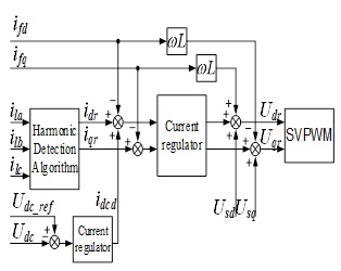 ) shows the control scheme of three-phase three-wire APF. Here, Udc_ref is the reference value of DC voltage, Udc is the sampling value, Idcd is a regulating signal that is the difference between Udc_ref and Udc through voltage regulator. And idcd is added to the d-axis component of the output current reference. In fact, the d-axis DC component idcd, which represents the fundamental frequency components of the active currents, causes the real power exchange between AC and DC side.
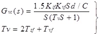
Before designing the voltage controller, the conversion factors from AC input current id`iq to DC output current idcd must be known. According to the mathematical model of APF, it has idc=1.5(Sdid+Sqiq). Here, the relationship between AC and DC current is time-varying because of two variables Sd and Sq. To simplify the process and design it with thelinear method, it is believed that iq has completed the transient process reaching to 0 before a large change on the DC voltage, in which the value of iq equals 0 in steady state, and iq changes slightly in a dynamic process due to the current closed-loop. Based on this, the d-axis block diagram of the voltage outer-loop control can be seen in Fig. (2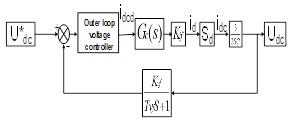 )
)
 |
Fig. (1) The control scheme of three-phase three-wire APF. |
 |
Fig. (2) Axis block diagram of the voltage. |
Where Gc(s) is the closed-loop transfer function of inner current, Tvf means the delay time constant of voltage feedback path (switching frequency is 9600Hz, or delay time is 104 us). Kvf means the amplification factor of the voltage feedback path (taking 1). Kif means the sampling coefficient of the output current (taking 16.384), and the capacitor C takes 20 mF.
Due to the second-order of the transfer function of current closed-loop Gc(s), it is better to lower the order of Gc(s) so as to make the synthesis of the voltage loop easier. The process is shown as follows:
The transfer function of the inner current control loop is:
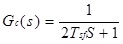 |
(1) |
The open-loop transfer function without the controller is:
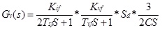 |
(2) |
Because Tvf and Tsf are time constant, so equation (2) can be simplified as bellow:
 |
(3) |
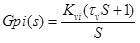
The transfer function of PI controller is:
 |
(4) |
Thus, the open-loop transfer function with PI controller is:
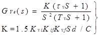 |
(5) |
From the analysis above, it can be seen that equation (5) is a typical type II system, the controller parameters can be designed according to Oscillation index method. The key point of the Oscillation index method is to select parameters according to the practical engineering requirements for the closed-loop relative resonance peak. Based on this, it can be ensured the system performance index does not exceed a specified value, i.e. the maximum overshoot is not greater than a certain limit value, the corresponding phase margin is the biggest, and the amplitude margin is the best, also the adjusting time is the shortest. Fig. (3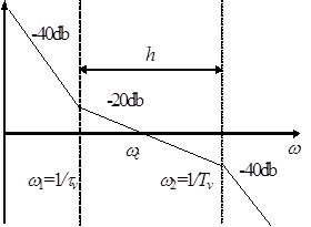 ) shows the Bode diagram of the open-loop voltage with PI controller.
 |
Fig. (3) Bode diagram of the open-loop voltage with PI controller. |
From the Bode diagram in Fig. (3), a best fit between the two parameters can be found based on the minimum peak norm of amplitude-frequency characteristics in Oscillation index method. When the closed-loop resonant peak Mr reaches to the minimum, the relationship of each variable is obtained as:
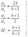 |
(6) |
The key to design the voltage loop is determining the bandwidth h. Practical experience shows that the width of medium-frequency h varies generally between 3 to 10. In addition, a larger h does no significant effects on decreasing Mr. When h=constant, it can be derived as:
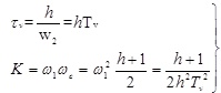 |
(7) |
So the parameters of the voltage controller can be gotten.
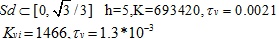 |
The PI controller of the voltage outer-loop is:
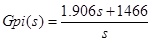 |
(8) |
3. THE INFLUENCE OF DC VOLTAGE ON POWER LOSS
The power loss of APF mainly includes the following two aspects: the switching loss of PWM inverter and the output inductor hysteresis loss, copper loss, etc.
The output current of APF is higher harmonics, and including some switching ripple current. In general, the switching frequency is much higher than that of the output current, so the output inductor hysteresis loss is mainly proportional to the size of the switching ripple current as well as the area surrounded by the magnetization curve of the magnetic material. When magnetic material with small magnetization curve area and high permeability, such as amorphous material, is selected, the output inductor hysteresis loss will be reduced to a relatively low percentage.
However, switching loss of PWM inverter actually contains IGBT switching loss, the diode reverse recovery loss, and the conduction loss of IGBT as well as the diode.
Furthermore, the IGBT conduction loss is proportional to the drop voltage and the flowing current, and the drop voltage increases with the flowing current. So it can be concluded that the conduction loss of IGBT increases as the APF output current rises. And this is also suitable to the diode conduction loss.
The IGBT switching loss includes turn-on and turn-off loss, and both the two components increases with DC voltage in case of the constant flowing current and switching frequency. It does also apply to the diode reverse recovery loss.
The main components of these losses mentioned above are IGBT switching loss and diode reverse recovery loss. With the constant switching frequency and output current, any increase/decrease in DC voltage causes a relative increase/decrease in the power loss of APF.
In addition, due to the complexity of the switching loss simulation, the relationship between DC voltage and the power loss of APF will be verified depending on experiments.
4. THE INFLUENCE OF DC VOLTAGE ON COMPENSATION PRECISION
Without considering the influence of current regulator and the error of harmonic extraction algorithm, the capability of compensating harmonic currents of nonlinear load is important to be considered in order to analyse the compensation performance of APF. Based upon the topology structure of APF and neglecting the inverter loss, according to equation (9), the output current of APF is relevant to the inductor drop voltage which can be easily obtained by a simple subtraction of the midpoint voltage of PWM inverter arms and the grid voltage.
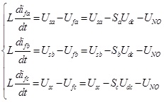 |
(9) |
In order to quantitatively analyse further, assuming the system is symmetrical, Usm is the peak of the grid phase voltage, and ω is the power system angular velocity. And the three-phase source voltage can be defined as:
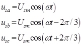 |
(10) |
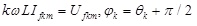
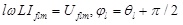
Suppose the load is the three-phase uncontrolled rectifier with LR connection. According to the characteristic of the nonlinear load, it only exists 6n±1 harmonic orders in the load current, where 6n+1 is the positive sequence component, and 6n-1 is the negative one. Without considering the influence of current regulator and the error of harmonic extraction algorithm, the APF output current and the PWM inverter output voltage can be established as bellow:
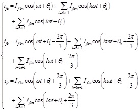 |
(11) |
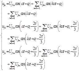 |
(12) |
Here, If1m is the peak of APF output fundamental current, Uf1m is the peak of PWM inverter output fundamental voltage, Ifkm and Iflm mean the peak of APF output the k-th and l-th harmonic currents respectively, Ufkm and Uflm represent the peak of PWM inverter output the k-th and l-th harmonic voltages respectively, θ and φ signify the initial phase angle of each order component.
According to the definition of Park transform, a space vector synthesized by any three-phase variables xa`xb and xc can be illustrated mathematically as:
 |
(13) |
Then equations (4-1) can be transfer to equation (14):
 |
(14) |
Substitute equations (10) ` (11) ` (12) into equations (13) ` (14), we can get:
 |
(15) |
Obviously, the real and the imaginary part are equal in both sides respectively, and it is true for any ωt. So equation (15) can be simplified as:
 |
(16) |
 |
(17) |
 |
(18) |
According to equations (16 - 18), the harmonics of APF output current depends on each harmonic of PWM inverter output voltage and the voltage of the power grid.
Moreover, PWM inverter amplitude modulation ratio M is the ratio of the length of output voltage resultant vector Ufr and half of the average DC voltage Udc.
 |
(19) |
 |
(20) |
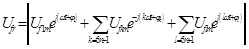
Considering compensating the load in the worst case, the maximum value of Ufr can be expressed by equation (21).
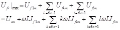 |
(21) |
The maximal Ufr is the biggest PWM inverter output voltage necessary to compensate harmonic currents of nonlinear load under the worst condition. As for PWM inverter, an APF must output the voltage vector exceeding the maximum, so as to completely compensate harmonic currents of nonlinear load. Based on the above analysis and combining equations (19) and (21), we can get:
 |
(22) |
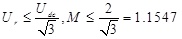 |
(23) |
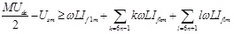
Equation (23) indicates the linearity range of space vector modulation. Suppose that the amplitude modulation ratio M is constant and equals to or more than 1.1547during the operation of APF, then formula (22) can be transformed to:
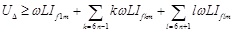 |
(24) |
 |
(25) |
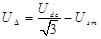
From the analysis of the above two equations, it can be concluded that:
(1) UΔ determines the capacity of APF output harmonic current;
(2) With the same harmonic current RMS, the higher the order of harmonics is, the bigger PWM inverter output harmonic voltage is required;
(3) The influence on PWM inverter output harmonic voltage caused by the size of output inductor L is a factor to be considered when designing L.
Here to analyse the influence of UΔ on the capability of APF output harmonic current. Assume that the designed output inductor L=0.3mH, the rated grid phase voltage RSM Usn=220V, and the nominal DC voltage Udcn=700V.Based on the above design conditions, the compensation performance of APF can be achieved to meet the requirements. If the grid voltage fluctuates in a range of 90%-110%, the capability of APF output harmonic current varies with the changed UΔ.
As shown in Fig. (4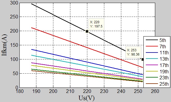 ), the vertical axis shows the peak of the maximum k-th harmonic current that APF can output with the corresponding grid voltage. When Us =220V, the peak of maximum 5-th harmonic current is 197.5A, and when Us=1.1Usn=242V, the peak one is 131.4A, and it is 263.6Awhen Us=0.9Usn=198V. Comparing the grid voltage 1.1Usn with Usn, the capacity of APF output the maximum 5-th harmonic current declines by almost 33.5%. There is a similar relationship for other harmonics.
 |
Fig. (4) The capability of APF output harmonics when the grid voltage varies. |
In conclusion, without considering the impact of current regulator and the error of harmonic extraction process, UΔ will influence on the compensation performance of APF. In the linear modulation range and with the constant modulation ratio, increasing DC voltage can enhance the compensation performance of APF, while decreasing DC voltage can reduce the performance. Similarly, any increase/decrease in the grid voltage leads to a relative decrease/increase on the APF compensating performance.
5. OPTIMIZING DC VOLTAGE CONTROL BY ADOPTING THE DROOP REGULATOR
5.1. Design of the Droop Regulator
In industrial fields, the line voltage generally has no sudden changes, while it tends to be on large fluctuation (range:90%-110%) over a long period of time. The designed DC voltage is bigger in the worst case of grid voltage when taking Us = 1.1Usn. A larger DC voltage can cause more power loss according to the analysis above. However, if the grid nominal voltage is used in the design of the DC voltage, it is likely that the compensation performance of APF cannot be ensured with the increase of the grid voltage.
Assuming that at rated grid voltage, the compensation performance of APF can meet the expected requirement by using the designed DC voltage rating. A droop regulator can be designed to control DC voltage reference with the grid voltage fluctuating according to equation (25). Increasing DC voltage can enhance the compensation performance of APF with a higher grid voltage, while decreasing DC voltage can reduce the power loss of APF with a lower grid voltage. Thus, the integrative optimization of APF’s power loss and compensation performance is implemented.
The droop regulator can be expressed by the following equations (26) and (27):
 |
(26) |
 |
(27) |
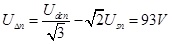
On the basis of the grid voltage fluctuating in the range of ±10% (APF is no longer working if the grid voltage is out of this range), the droop regulator curve can be drowned according to the above two equations. As shown in Fig. (5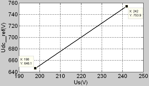 ), the range of DC voltage is 646V-754V.
 |
Fig. (5) Controlling DC voltage by the droop regulator. |
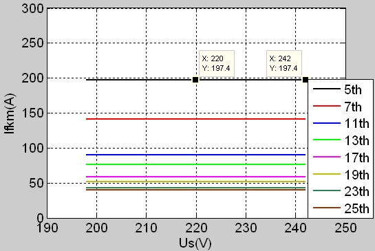 |
Fig. (6) The capability of APF output harmonics current when the grid voltage varies by using the droop regulator. |
Further, the influence on the capacity of APF output harmonic current caused by the grid voltage fluctuating after using the droop regulator is analysed. It is observed from Fig. (6 ) that the grid voltage fluctuating does not affect the capability of APF output harmonic current in comparison with no droop regulator.
The control strategy of APF by using the droop regulator is shown in Fig. (7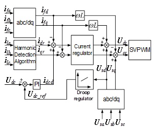 ).
).
 |
Fig. (7) The control strategy of APF by using the droop regulator. |
5.2. Simulation Analysis
This section analyses the relationship among DC voltage`the grid voltage and the compensation performance through MATLAB-SIMULINK simulations. The harmonic source is the three-phase uncontrolled rectifier with resistive load, the RMS of power voltage rating is 380V, and DC voltage rating is 700V. The above analysis is verified under three working conditions.
In Fig. (8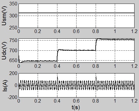 ), the grid voltage remains invariable, and the DC voltage reference is 646V in 0-0.4s, or 700V in 0.4-0.8s, or 754V in 0.8-1.2s.
 |
Fig. (8) Waveforms of the grid phase voltage peak Usm`DC voltage Udc and the compensated source current Is in the first working condition. |
It can be seen from Fig. (9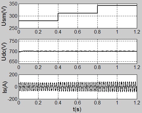 ) that when maintaining the DC voltage constant, the grid voltage is 90% of the rating in 0-0.4s, 100% in 0.4-0.8s, and 110% in 0.8-1.2s.
 |
Fig. (9) Waveforms of the grid phase voltage peak Usm`DC voltage Udc and the compensated source current Is in the second working condition. |
As seen from Fig. (10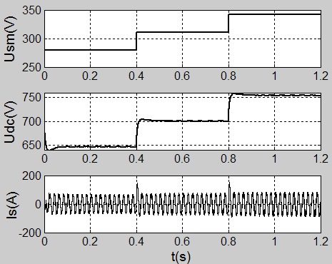 ), in case of using the droop regulator to control DC voltage, the grid voltage is 90% of the rating in 0-0.4s,100% in 0.4-0.8s, and110% in 0.8-1.2s.
 |
Fig. (10) Waveforms of the grid phase voltage peak Usm`DC voltage Udc and the compensated source current Is in the third working condition. |
According to the simulation results, the performance of APF system in different conditions is analysed as listed in Table 1. Us% means the ratio of the real value to the rating of the grid voltage, Il means the RMS of load current, and THDI is the total harmonic distortion of current.
For case one, with the constant grid voltage Us, THDI decreases as Udc increases. For case two, with the fixed DC voltage Udc, THDI increases as Us increases. The two simulation conditions both show that the change of UΔ influences the compensation performance of APF. For case three, compared to case two, the compensation performance of APF can be improved as the grid voltage increases with the help of the droop regulator to control DC voltage.
5.3. Experimental Verification
A series of experiments are employed for the developed APF system to testify the above theoretical analysis. The APF system parameters are given in Table 2. The nonlinear load is three-phase uncontrolled rectifier with LR connection. The DC-link inductor and the resistor are designed as 0.5mH and 5Ω, respectively.

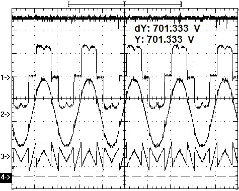
Firstly, verify the relationship between compensation performance`power loss and DC voltage. The grid phase voltage maintains 220V, DC voltage reference values are650`700and750Vcorresponding to the first`second and third working condition, respectively and the experiment results are shown in Figs. (11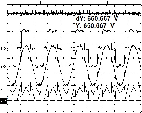 -13
-13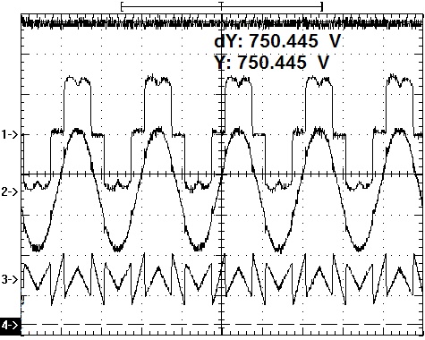 ).
).


Secondly, verify the influence on the compensation performance of APF caused by the grid voltage fluctuating. The DC voltage reference value is700V, and the grid phase voltage is 232V, which is corresponding to the forth condition, shown in Fig. (14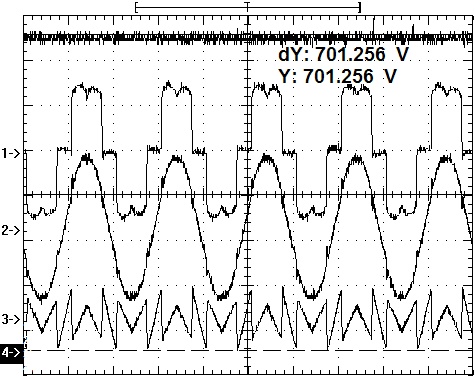 ).
).
Finally, verify the influence on the compensation performance of APF when adjusting DC voltage with the droop regulator. The grid phase voltage is 232V, and the output DC voltage reference of the droop regulator is 720V, corresponding to the fifth condition, shown in Fig. (15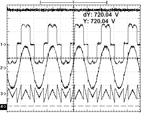 ).
).

According to the experimental results, the performance of APF system in different conditions is analysed as listed in Table 3. Us is the grid phase voltage, Il is the RMS of load current, and THDI is the total harmonic distortion of current, Ploss is the APF conversion system loss.
In summary, analysis of case 1`2 and 3, THDI decreases and Ploss increases during the DC voltage rises if Us is constant. From case 2 and 4, it can be concluded that if the DC voltage has no change, THDI increases with the increased Us. Compared case 4 with 5, adjusting DC voltage with the droop regulator can improve compensation performance of APF as Us increases. Finally, comprehensive analysis of these five conditions, it is believed that any decrease in the grid voltage Us can cause the power loss of APF when adjusting DC voltage with the droop regulator.

And finally, the dynamic performance of APF is verified when the DC-link voltage is suddenly changed. As shown in Fig. (16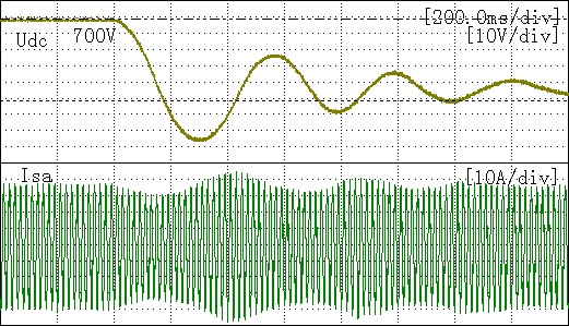 ), when the grid phase voltage maintains 220V, the DC voltage surges from700V to 650V. Besides, the compensated grid current has some fluctuation but little in the overshoot process.
 |
Fig. (16) The dynamic performance of APF when DC voltage is suddenly changed. |
CONCLUSION
This paper firstly describes the design of DC voltage regulator in detail, and then the influence on the power loss and compensation performance of APF caused by DC voltage is analysed. According to the analysis`simulations and experiments, some important results have been gotten. Any increase/decrease in DC voltage can cause increase/decrease in the power loss of APF. Besides, without considering the influence of current regulator and the error of harmonic extraction process, the compensation performance of APF increases with the rising of DC voltage, as well as it decreases as the grid voltage rises. A higher DC voltage can improve compensation performance with the increased grid voltage. Also, on the basis of guaranteeing the compensation performance, a lower DC voltage can reduce power loss when the grid voltage decreases. Therefore, a new control strategy for adjusting DC voltage with the droop regulator is proposed. Adjusting DC voltage with the use of droop regulator can keep UΔ constant as the grid voltage fluctuates, and what can be achieved the integrative optimization of APF’s power loss and compensation performance.
CONFLICT OF INTEREST
The authors confirm that this article content has no conflict of interest.
ACKNOWLEDGEMENTS
Declared none.
REFERENCES
| [1] | A. Tarkiainen, R. Pollanen, M. Niemela, and J. Pyrhonen, "DC-link voltage effects on properties of a shunt active filter", In: IEEE Power Electronics Specialists Conference, Aachen, Germany, 2004, pp. 3169-3175. [http://dx.doi.org/10.1109/PESC.2004.1355342] |
| [2] | G. Zhao, J. Liu, and Y. Xin, "Analysis and specification of DC side voltage in parallel active power filter regarding compensation characteristics of generators", In: IEEE Power Electronics Specialists Conference, Rhodes, Greece, 2008, pp. 3495-3499. [http://dx.doi.org/10.1109/PESC.2008.4592496] |
| [3] | X. Huang, J. Liu, and Z. Hui, "A simplified shunt APF model based on instantaneous energy equilibrium and its application in DC voltage control", In: IEEE Power Electronics Specialists Conference, Rhodes, Greece, 2008, pp. 2235-2241. [http://dx.doi.org/10.1109/PESC.2008.4592274] |
| [4] | A. Chaoui, J.P. Gaubert, F. Krim, and L. Rambault, "On the design of shunt active filter for improving power quality", In: IEEE International Symposium Industrial Electronics, Cambridge, UK, 2008, pp. 31-37. [http://dx.doi.org/10.1109/ISIE.2008.4677277] |
| [5] | W. Shi, Q. Wang, and Q. Xing, "Research on current tracking control method for four-leg APF", J. Electr. Instrument, vol. 12, pp. 1162-1169, 2013. |
| [6] | Wenqiang Li, and Yang Lu, "Research and implementation of direct measurement technique of current speed", J. Electron. Meas. Instrum., vol. 26, no. 1, pp. 43-48, 2012. [http://dx.doi.org/10.3724/SP.J.1187.2012.00043] |
| [7] | G. Jie, D. Jiang, and Y. Zhou, "AC and DC current hybrid control strategy for modular multilevel converter", Dianli Xitong Zidonghua, vol. 35, no. 7, pp. 42-47, 2011. |
| [8] | M. Qiao, Y. Xia, and J. Liang, "Research on PI control based compound controller applying to shunt active filter", Power Syst. Prot. Control, vol. 41, no. 14, pp. 54-59, 2013. |
| [9] | M. Ban, S. Ke, and J. Shen, "A novel circulating current suppressor for modular multilevel converters based on quasi-proportional-resonant control", Dianli Xitong Zidonghua, vol. 38, no. 11, pp. 85-89, 2014. |
| [10] | J. Li, X. Wu, and X. He, "Research on the active power damping control of LCL-APF based on concentrated compensation", Power Syst. Prot. Control, vol. 43, no. 5, pp. 101-106, 2015. |
| [11] | Z. Huang, B. Xu, and L. Shen, "New current double closed loop control strategy of LCL grid-connected inverter", Power Syst. Prot. Control, vol. 40, no. 17, pp. 1-5, 2012. |
| [12] | Q. Liu, L. Peng, and Y. Kang, "A novel design and optimization method of an LCL filter for a shunt active power filter", IEEE Trans. Ind. Electron., vol. 61, no. 8, pp. 4000-4010, 2014. [http://dx.doi.org/10.1109/TIE.2013.2282592] |
| [13] | Z. Qu, and Y. Wang, "Four-terminal Impedance Bridge based on current-comparator", Yiqi Yibiao Xuebao, vol. 32, no. 9, pp. 1987-1992, 2011. |
| [14] | X. Zhang, Y. Liu, and W. Rui, "A novel active damping control strategy for PWM converter with LCL filter", Trans. China Electro Tech. Soc., vol. 26, no. 10, pp. 188-192, 2011. |
| [15] | "KAURA V. A novel control to actively damp resonance in input LC filter of a three-phase voltage source converter", IEEE Trans. Ind. Appl., vol. 33, no. 2, pp. 542-550, 1997. [http://dx.doi.org/10.1109/28.568021] |
| [16] | Z. Lin, D. Jiang, and Y. Zhou, "Control and modulation for APF-STATCOM based on cascaded H-bridge converter", Power Syst. Prot. Control, vol. 42, no. 7, pp. 91-96, 2014. |