- Home
- About Journals
-
Information for Authors/ReviewersEditorial Policies
Publication Fee
Publication Cycle - Process Flowchart
Online Manuscript Submission and Tracking System
Publishing Ethics and Rectitude
Authorship
Author Benefits
Reviewer Guidelines
Guest Editor Guidelines
Peer Review Workflow
Quick Track Option
Copyediting Services
Bentham Open Membership
Bentham Open Advisory Board
Archiving Policies
Fabricating and Stating False Information
Post Publication Discussions and Corrections
Editorial Management
Advertise With Us
Funding Agencies
Rate List
Kudos
General FAQs
Special Fee Waivers and Discounts
- Contact
- Help
- About Us
- Search


The Open Electrical & Electronic Engineering Journal
(Discontinued)
ISSN: 1874-1290 ― Volume 13, 2019
Modeling Research of Dielectric Permittivity Tensor in Unipole Cylindrical Plasma Antenna System Excited by Surface Wave
Jin Hongying*
Abstract
The paper applies Bolzmann equation and gas molecular dynamics theory and analyzes the motion state of plasma internal particle and electromagnetic field distribution around antenna through modeling, It based on the cylindrical unipolar surface wave plasma antenna structure. Modeling calculation results of plasma antenna local dielectric tensor shows that the model method can reflect accurate dielectric relatively especially its each component of tensor changes. It is an exact method that calculate dielectric tensor of cylindrical surface wave excited plasma antenna.
Article Information

Identifiers and Pagination:
Year: 2016Volume: 10
First Page: 36
Last Page: 45
Publisher Id: TOEEJ-10-36
DOI: 10.2174/1874129001610010036
Article History:
Received Date: 9/8/2015Revision Received Date: 22/9/2015
Acceptance Date: 24/11/2015
Electronic publication date: 29/04/2016
Collection year: 2016
open-access license: This is an open access article licensed under the terms of the Creative Commons Attribution-Non-Commercial 4.0 International Public License (CC BY-NC 4.0) (https://creativecommons.org/licenses/by-nc/4.0/legalcode), which permits unrestricted, non-commercial use, distribution and reproduction in any medium, provided the work is properly cited.
* Address correspondence to this author at the Computer College of China West Normal University, Shida Road No. 1, ShunQing District, Nanchong, Sichuan, 637002, China; E-mail: jinhongying_cwnu@163.com
| Open Peer Review Details | |||
|---|---|---|---|
| Manuscript submitted on 9-8-2015 |
Original Manuscript | Modeling Research of Dielectric Permittivity Tensor in Unipole Cylindrical Plasma Antenna System Excited by Surface Wave | |
1. INTRODUCTION
In the recent research of plasma antenna, the plasma is generally simplified as axial linear distribution of uniform distribution density cylindrical. Small power signals is transmited in the form of surface wave propagation along the plasma column, and it has a small surface depth, this mode of the electromagnetic waves are similar to the metal unipolar antenna transmission modes [1T. Anderson, Plasma Antenna, Artech House, 2011, pp. 79-112.-5Y.I. Burykin, S.M. Levitskiy, and V.G. Martynenko, "Establishing highly conductive path in gas by thermal guidance of discharge", Radio Eng. Electron. Phys., vol. 20, pp. 86-88, 1975.].
Therefore Borg Harris Rayner [6J.P. Rayner, A.P. Whichello, and A.D. Cheetham, "Physical characteristics of plasma antennas", IEEE Trans. Plasma Sci., vol. 32, no. 1, pp. 269-281, 2004.
[http://dx.doi.org/10.1109/TPS.2004.826019] , 7G.G. Borg, J.H. Harris, N.M. Martin, D. Thorncraft, R. Milliken, D. G. Miljak, B. Kwan, T. Ng, and J. Kircher, "Plasmas as antennas: Theory, experiment and applications", Phys. Plasmas, vol. 7, no. 7, pp. 2198-2202, 2000.
[http://dx.doi.org/10.1063/1.874041] ] simplified the high-density plasma antenna with the same similar electric and surface current distribution form with metal antenna.
However, the simplified solution above mentioned has many obvious limitations, first according to dual polarity effect, the plasma cylindrical radial density distribution is uneven, the resonance absorption also exists in antenna medium border surface and changes the wave space dispersion thus increases energy loss of wave. The inhomogeneity density of wave in radial direction makes the electromagnetic field distribution has no analytical solution forms, thus it should be used the numerical method to analyze. Papers [8Z. Dai, S. Liu, and Y. Chen, "Development and investigation of reconfigurable plasma antennas", In: 2010 International Conference on Microwave and Millimeter Wave Technology, 2010, pp. 1135-1137.
[http://dx.doi.org/10.1109/ICMMT.2010.5525072] -11"Self-consistent model for the characterisation of plasma ignition by propagation of an electromagnetic wave to be used for plasma antennas design", In: European Conference on Antennas and Propagation, 2010, pp. 12-16.] analyzes the cylindrical plasma electron density axial distribution, the related research when the plasma axial density dispersion is uneven, and the infuence of the electromagnetic field distribution to the antenna parameters etc.
As for axial density is uneven dispersion (linear attenuation) in plasma column, there is no exact calculation and analysis of the approximate electric field each direction of axial distribution now. The uneven Axial dielectric tensor also can change the intensity of electromagnetic field in spatial variation. Therefore, a reasonable calculation method of dielectric tensor distribution is an important research content in the plasma antenna research work .
2. ANALYSIS OF MODELING THEORY
In unipole surface wave plasma antenna systems, small signal transmits in surface wave form in antenna surface, the antenna characteristics is determined by its internal state of plasma, its dielectric constant tensor is the important influence factor of antenna parameters performance. Due to the role of inductive magnetic field, the plasma antenna coefficient present the anisotropic and has the dielectric tensor.
The dependent relationship of dielectric tensor εi,j(ω,k) between frequency ω is the dispersion relationship, while electric tensor εi,j(ω,k) is in the dependence of the vector k, according to the space dispersion relationship.
Plasma antenna is belong to the weak cold magnetized plasma, so the DeBai shielding length λDE is very short, thus if don't take the influence of space dispersion into consideration. Dielectric tensor modeling is according to the electromagnetic field distribution characteristics from the axial and radial direction, the plasma antenna is divided into several dielectric tensor approximation of uniform distribution area, and then make the correlation analysis research and rational calculation.
2.1. Dielectric Tensor Calculation Model
In the one end of cylinder surface wave plasma antenna is the high-power RF coupling excitation source, the Rf power is coupled into antenna. Metal coil is approximately considered as a series of concentric circles, RF coil generated electromagnetic waves along the radial into plasma and electromagnetic waves along the coil has little changes. Unipolar incentive cylindrical plasma antenna experiment device is as the Fig. (1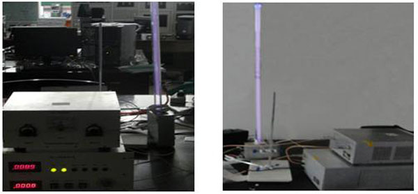 ) shows.
 |
Fig. (1) The unipolar incentive column plasma antenna. |
As the Figs. (2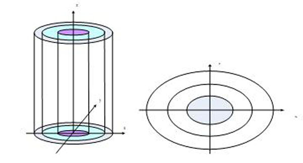 , 3
, 3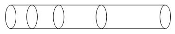 ) shows, in the antenna system the induction electric field is reverse symmetrical, the inductive magnetic field along is axial symmetry. When the plasma density is not very high, the inductive magnetic field and the induction electric field around the antenna is attenuation distribution.
 |
Fig. (2) The radial layered structure and projection schemes. |
Cylindrical radial plasma antenna can be idivided into many small cylindricals parts, as Fig. (2) shows, in each cylindrical plane the plasma inside can be regarded as evenly distributed. When the plasma density is high, the small power of transmitting signals on the plasma antenna has low surface depth. The plasma dielectric tensor distribution, according to its distribution along the plasma antenna, which then can be calculated by stratification subsection integral calculation model, just as Fig. (3) shows.
 |
Fig. (3) The axial piecewise structure schematic drawing. |
Assumptions for the Modle is as following:
- Along the axial intercepted cylindrical plasma antenna unit length within the cyclinder surface, the plasma antenna is divided into a series of concentric circles, projection of each circle the plasma is homogeneously distributed. Hence, reference to plasma radial distribution characteristics, the cylindrical plasma antenna along the axial can intercept multiple cylindrical surface, on each cylindrical inside plasma can be regared as evenly distributed.
- Driving Rf power frequency is far outweigh the ion plasma oscillation frequency.
- As the plasma density is high, the wall near the surface of scab cylindricald is very thin and is far less than the diameter of the antenna length, therefore sheath of the plasma can be neglected, at the same time the hot movement of electron is not considered in plasma.
- In the border, electron is regared as come into the plasma from the area |x > b, so in the dynamic equation the area can be facilitated expanded to |x| → ∞.
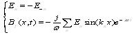
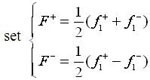
- The time factor of physical quantities is e-jωt. So the Fourier series express of induction electric field is as follows:
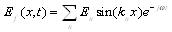 |
(1) |
Where kn = nπ / 2a is Fourier space wave sagittal number, through maxwell equation
 then get:
 |
(2) |
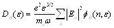
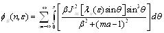
Make the hypothesis that the inside small specific area of plasma antenna shows uniform distribution, the low-frequency magnetized plasma can be analyzed through molecular dynamics and relevant theorie, the dielectric tensor is composed of isotropic plasma dielectric constants, each component of it can be obtained through the corresponding formulas.
2.2. Analysis of Molecular Dynamics Theory
In the low temperature plasma antenna inductive magnetic field is weak, the molecule distribution function is close to isotropic distribution. Through dynamic model based on studying of the stationary processes and distribution characteristics of the electromagnetic wave with plasma, get the interaction between the relations, so as to deduce the external electric field, magnetic field changes conditions and plasma dielectric tensor distribution of mutual relationship.
The premise of dynamics theory research is, collision frequency is far below that of electric field frequency, so each collision of particle is in a relatively stable outside electric field. In the process of deducing the Bolzmann equation, assuming the collision time ∆t is much smaller than 2π/ω that of the cycle falternating field, so each collision occurs in a constant electric field, the pemise under the radio spectrum condition is satisfied, because molecular radius is about 10-8cm, the average speed of electron is largerer than 107cm/s, the electron impact time is about ∆t < 10-15s.
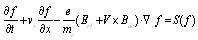
Make the hypothesis that electronic speed distribution function is satisfied with the following Bolzmann equations as type (3):
 |
(3) |
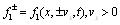
For low pressure high-frequency discharge, make the following hypothesis as type (4):
| f = f0 + f1 | (4) |
f0 is the seperately balance distribution and f1 is the disturbance one, which is satisfied with the distribution |f1| ≤ |f 0|, put (4) type into (3) type get the following type (5):
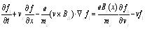 |
(5) |
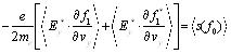 |
(6) |
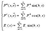
Solving the disturbance, the speed distribution function f1, using cylindrical coordinates as

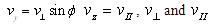 are seperately the vertical factor and parallel factor of magnetic field, the direction angel of speed space is Ø = tan-1(vy / vx), so get the type (7):
 |
(7) |
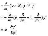
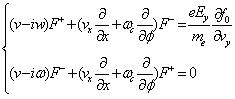
ωc = eB/me is electron cyclotron rate. Make the assumption that
Equation (2) can be written as the type (8):
 |
(8) |
 |
(9) |
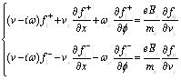
The equation (8) can be further written as type (10):
 |
(10) |
Assuming in boundary region electron happening “mirror” reflect, so get the following type (11):
 |
(11) |
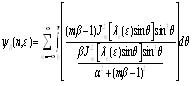
After a series deducing get the disturbance distribution function is as type (12).
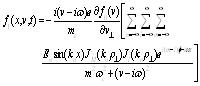 |
(12) |
 is electron cyclotron radius, JM(x) is the first kind Bessel function, J'M(x) is symbol of d[JM(x)] / dx m, l is integer. After getting disturbance distribution function, put it into (6) and (7) type then get the following differential equations is as type (13):
 |
(13) |
Among them,
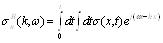
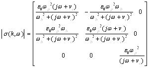
So the conductivity in Fourier space can be expressed is as type (14):
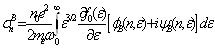 |
(14) |
So electronic and electromagnetic interaction function is as the following type:
 |
(15) |
For specific distribution area, plasma distribution is approximate uniform, such as the time and the spatial change of external incentives electric field, current and conductivity can be written as (16) and (17) type, which is calculated by a particular space within the dielectric tensor.
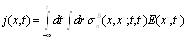 |
(16) |
 |
(17) |
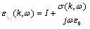 |
(18) |
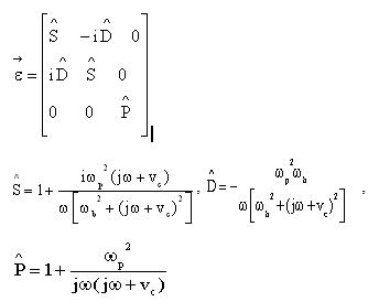
Among them, ||I|| is the three ranks unit matrix
 |
(19) |
ω b is electron cyclotron frequency, ωp is plasma angle, vc is collision frequency, ω is the frequency of signal source. For convenience, the dielectric tensor type (19) can be written as the type (20):
 |
(20) |
3. NUMERICAL CALCULATION PROCESS OF MODEL
Under the initial condition, according to external electromagnetic field distribution, the plasma length, signal frequency, plasma radius, the amplitude of the antenna surface current, the plasma density of the unit length of the antenna is known. When plasma dielectric tensor changes, the electromagnetic wave propagation will caused the change of working frequency, direction graph characteristics of antenna etc. The calculation method process is as follows:
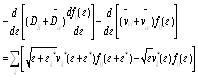
From the initial condition plasma density n0 and pressure p, assuming the electronic energy distribution function is f 0(ε), the first step is to solve electromagnetic equations to get En, then get the energy diffusion coefficient DE, and through solving the electronic dynamic equation get the new distribution functions f 0(ε). The second step is to judge whether the f 0(ε) is convergence, if not, the calculation is continued to get a new En, until a stable outcome , the last step is a series of derivation f 0(ε), and get the spatial distribution of electromagnetic field. After getting the plasma density (plasma frequency), plasma collision frequency, internal and external radius, then the plasma antenna dielectric tensor can be calculated. The finite difference method can be exprssed as type (13), the type can be simplified as the type (21):
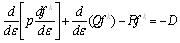 |
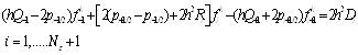
(21) |
p = p (ε, f k-1), Q = Q(ε, f k-1), D = D(ε, f k-1), R = R(ε), k is the number of alternate, put energy ε ino Eε split, the interval is H.
So, on the first grid points i = 1,....Nε the energy is expressed as type (22):
| εi = (i - 1)h | (22) |
Then its abbreviations and differential form can be expressed the type (23):
fi k = f k (εi), pi = p(εi), Qi = Q(εi), Ri = R(εi), Di = D(εi)
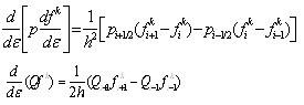 |
(23) |
The number of linear equations is Nε:
 |
(24) |
Equations (24) is a coefficient diagonal matrix, it can be solved though diagonal matrix and the process is iterative, wnen it get satisfied convergence outcome, the iterative process is end. The iteration process normalization conditions must be satisfied with the type (25) below:
 |
(25) |
After getting the expression of f 0, available space distribution and power distribution of the electromagnetic energy, then the distribution of antenna dielectric tensor can be worked out.
Figs. (4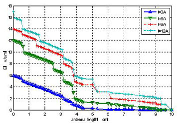 , 5
, 5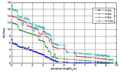 ) show the electromagnetic field spatial distribution of the simple self-consistent model and linear model along the antenna, the figure show that, outcome of linear model present exponential attenuation, and with the increase of electric current, only with intensity corresponding increase, and space distribution of shape has not changed. The self-consistent model presents some abnormal behavior, with discharging coil distance increases, electric field reduces to a minimum attenuation, then increases slowly to a larger value again after its decreasing, especially along with the increase of electric current, the abnormal behavior is increasingly clear.
 |
Fig. (4) The electric maxwell's distribution. |
 |
Fig. (5) The model the distribution of electric field. |
The reasons is in low pressure plasma, electron gains energy inner electric field nearfrom the coil, under the force v × Brf, electron is in radial motion, when the electronic speed and electromagnetic wave speed is approximate the same, there happens Rang-Dao hinder phenomenon, which causes the electric abnormal behavior. Experimental tests also shows the abnormal behavior of electric field mentioned above, so dynamics model can more accurately reflect the plasma antenna electric field around, while ordinary model cannot reflect the situation.
Figs. (6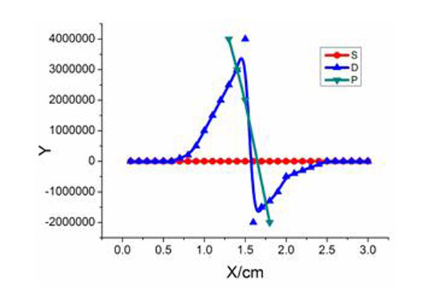 -8
-8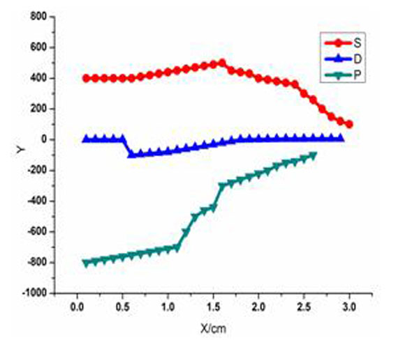 ) are the dielectric tensor curves get from the plasma antenna model. When the temperature of plasma is not too high, the plasma antenna dielectric tensor distribution is relatively smooth, but in some part of the antenna shows numerical high items. Under the certain motivating power, with the improvement of incentive frequency and antenna state gradually becomes stabilized, the dielectric tensor of each component distribution gradually becomes smooth and with no mutations items. So the dielectric tensor and its each component can be calculated through the model.
 |
Fig. (6) The dielectric tensor when incentive power is 30W and frequency is 25MHz. |
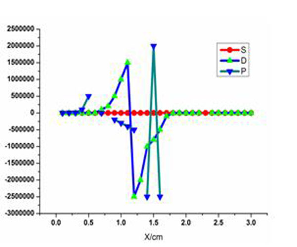 |
Fig. (7) The dielectric tensor when incentive power is 30W and frequency is 35MHz. |
 |
Fig. (8) The dielectric tensor when incentive power is 30W and frequency is 300MHz. |
CONCLUSION
The calculation of plasma antenna dielectric constant, especially when there exists inductive magnetic field around the plasma antenna, is a complicated problem. Simulation based on XFDTD software cannot reflect the effect of antenna internal particle movement and external incentives to dielectric tensor,so the method based on software has many limitations and has low precision. Only through micro-level modeling analysis of particle movement, the higher approximate results can be obtained.
CONFLICT OF INTEREST
The author confirms that this article content has no conflict of interest.
ACKNOWLEDGEMENTS
Declared none.
REFERENCES
| [1] | T. Anderson, Plasma Antenna, Artech House, 2011, pp. 79-112. |
| [2] | R. Kumar, and D. Bora, "A reconfigurable plasma antenna", J. Appl. Phys., vol. 053303, pp. 1-5, 2010. |
| [3] | Y.A. Lanlan, T. Yan, and B. Wang, "Axisymetric Surface-Wave Dispersion in Plasma Antenna", Vacuum Sci. Tech., vol. 24, pp. 424-426, 2004. |
| [4] | G. Zhao, Research of Basic Theory and Nonlinear Phenomena in Plasma Antennas., Center for Space Science and Applied Research: Beijing, 2007, pp. 70-101. |
| [5] | Y.I. Burykin, S.M. Levitskiy, and V.G. Martynenko, "Establishing highly conductive path in gas by thermal guidance of discharge", Radio Eng. Electron. Phys., vol. 20, pp. 86-88, 1975. |
| [6] | J.P. Rayner, A.P. Whichello, and A.D. Cheetham, "Physical characteristics of plasma antennas", IEEE Trans. Plasma Sci., vol. 32, no. 1, pp. 269-281, 2004. [http://dx.doi.org/10.1109/TPS.2004.826019] |
| [7] | G.G. Borg, J.H. Harris, N.M. Martin, D. Thorncraft, R. Milliken, D. G. Miljak, B. Kwan, T. Ng, and J. Kircher, "Plasmas as antennas: Theory, experiment and applications", Phys. Plasmas, vol. 7, no. 7, pp. 2198-2202, 2000. [http://dx.doi.org/10.1063/1.874041] |
| [8] | Z. Dai, S. Liu, and Y. Chen, "Development and investigation of reconfigurable plasma antennas", In: 2010 International Conference on Microwave and Millimeter Wave Technology, 2010, pp. 1135-1137. [http://dx.doi.org/10.1109/ICMMT.2010.5525072] |
| [9] | Z. Liang, Research on Electronical Function and Noise Mechanism of Plasma-column Antenna, Center for Space Science and Applied Research: Beijing, 2008. |
| [10] | P. Russo, "G. Cerri E. Vecchioni. Self-consistent model for the characterization of plasma ignition by propagation of an electromagnetic wave to be used for plasma antennas design", IET Microw. Antennas Propag., vol. 4, no. 12, pp. 2256-2264, 2010. [http://dx.doi.org/10.1049/iet-map.2009.0290] |
| [11] | "Self-consistent model for the characterisation of plasma ignition by propagation of an electromagnetic wave to be used for plasma antennas design", In: European Conference on Antennas and Propagation, 2010, pp. 12-16. |