- Home
- About Journals
-
Information for Authors/ReviewersEditorial Policies
Publication Fee
Publication Cycle - Process Flowchart
Online Manuscript Submission and Tracking System
Publishing Ethics and Rectitude
Authorship
Author Benefits
Reviewer Guidelines
Guest Editor Guidelines
Peer Review Workflow
Quick Track Option
Copyediting Services
Bentham Open Membership
Bentham Open Advisory Board
Archiving Policies
Fabricating and Stating False Information
Post Publication Discussions and Corrections
Editorial Management
Advertise With Us
Funding Agencies
Rate List
Kudos
General FAQs
Special Fee Waivers and Discounts
- Contact
- Help
- About Us
- Search


The Open Electrical & Electronic Engineering Journal
(Discontinued)
ISSN: 1874-1290 ― Volume 13, 2019
Design of a Vehicle Chassis Inspection Robot Based on WiFi Network
Ying Zhao*, Yongxiang Sui, Jinsen Hou, Qun Sun, Chong Wang
Abstract
Background:
The vehicle chassis inspection robot introduced in this paper is capable of realizing automatic tracking, obstacle avoidance, and video image acquisition. The robot can be connected to a computer, mobile phone or other terminals through a WiFi network built within the robot, so as to achieve real time control of the robot motion, and to display videos or images collected by the robot on the computer screen. The system is simple and easy to operate, with high stability, high flexibility, precise directional control, and can satisfy the requirements in harsh environment.
Methods and Materials:
This design adopts a STC11F32XE microcontroller as the core, uses an ultrasonic sensor to detect the road objects and calculate the distance to the objects, anticipates and avoids obstacle during processing. The camera performs image acquisition and returns the picture to help easy detection of automotive chassis and manual robot control. The robot uses an infrared sensor to realize automatic obstacle avoidance, and it controls the travel speed as well as automatic stop by changing the PWM duty cycle.
Conclusion:
Through this research, an intelligent vehicle parking inspection system has been developed.
Article Information

Identifiers and Pagination:
Year: 2017Volume: 11
First Page: 154
Last Page: 164
Publisher Id: TOEEJ-11-154
DOI: 10.2174/1874129001711010154
Article History:
Received Date: 12/01/2017Revision Received Date: 30/05/2017
Acceptance Date: 02/06/2017
Electronic publication date: 15/08/2017
Collection year: 2017
open-access license: This is an open access article distributed under the terms of the Creative Commons Attribution 4.0 International Public License (CC-BY 4.0), a copy of which is available at: https://creativecommons.org/licenses/by/4.0/legalcode. This license permits unrestricted use, distribution, and reproduction in any medium, provided the original author and source are credited.
* Address correspondence to this author at the School of Mechanical & Automotive Engineering, Liaocheng University, No. 1 Hunan Road, Liaocheng City, Shandong Province, P.R. China; Tel: 86-0635-8239270; Fax: 86-0635-8239968; E-mails: zhaoying008zy@163.com; zhaoying@lcu.edu.cn
| Open Peer Review Details | |||
|---|---|---|---|
| Manuscript submitted on 12-01-2017 |
Original Manuscript | Design of a Vehicle Chassis Inspection Robot Based on WiFi Network | |
1. INTRODUCTION
According to statistics, in recent years the growth rate of global industrial robot sales has been steadily maintained above 10%. Japan and Europe are the two bases of the robotics industry, for example, Yaskawa, Panasonic, the U.S. PMAC, and Siemens have become global monopoly of robotics products [1W. Tianmiao, T. Yong, and C. Yang, "Research status and development trends of the service robotic technology", Scientia Sin. Inf., vol. 9, no. 42, pp. 1049-1066, 2012.]. Robots in extreme working conditions are the inevitable products to replace human to carry out dangerous works or tasks difficult to complete. Usually extreme operating robots all consist of advanced sensor system, remote control system, mobility system, and control system, which can be classified as second-generation robots [2Z. Ran, L. Yanwen, and Z. Tieshi, "Present situation of researches and trend of development of micro-robots", J. Mach. Design, vol. 26, no. 2, pp. 1-2, 2009.].
At present, automobile chassis testing requires a specific testing site or elevator device to lift a vehicle for chassis inspection, while professional equipment and tools are rarely available. The most common tool, known as automobile chassis detector, is a simple lever with a camera mounted on the top and an electronic screen at the end, which should be carried by an operator when he goes below the vehicle bottom for inspection. Although this instrument can overcome the environmental constraints that limit chassis inspection, there are other limitations, for example the operator with such a tool in hand often have to squat or even lay on the ground. Besides, the videos taken from the handheld instrument may jitter, the screen installed on the instrument maybe difficult to observe, the instrument weight and size bring extra difficulties for the operating staff. There is large demand of automobile chassis testing equipment, however so far there is no significant development in this field.
The automobile chassis inspection robot was designed to replace human operator to complete the chassis detection work, by which means there is no need to have a lifting device to raise the vehicle and there is even no need for a specific testing site. The robot design utilizes mature WiFi network technology to transmit control signals to the robot and to collect images from the robot to the computer. The robot can be controlled by human operator for local inspection or track testing in a specific site, to perform automatic and comprehensive chassis testing [3H.W. Tsai, C.P. Chu, and T.S. Chen, "Mobile object tracking in wireless sensor networks", Comput. Commun., vol. 30, no. 8, pp. 1811-1825, 2007.
[http://dx.doi.org/10.1016/j.comcom.2007.02.018] ].
2. THE OVERALL DESIGN SCHEME OF THE CHASSIS INSPECTION ROBOT
As shown in Fig. (1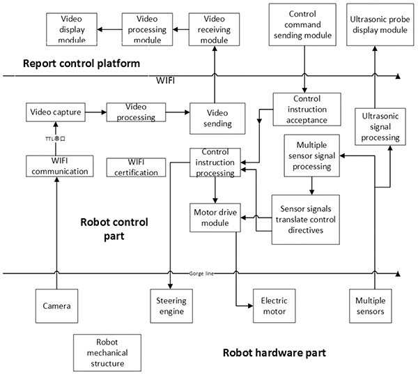 ), the robot hardware system comprises single-chip control system, sensor module, WiFi network communication module, camera platform, motor drive circuit, voltage regulator and power supply circuit, circuit protection system, servo motors, and LED lighting circuit.
 |
Fig. (1) Principle of the integrate robot system. |
The WiFi network module controls communication between the platform and the robot. The SCM system transmits the demands generated by the computers and other devices, and sends videos captured by the camera to the terminal equipment. The wireless network connects each module of the robot so that separate modules form the overall system of the vehicle chassis inspection robot. The SCM control system is the core of the robot that converts the control commands into robot actions, and controls each module work in coordinated actions. The control platform on one hand displays the video image information collected by the camera module of the vehicle chassis inspection robot, on the other hand, pressing the buttons on the control platform sends corresponding control commands to the robot SCM system via WiFi network so that robot control can be enabled. The motor drive circuit drives the motor rotation and is capable to achieve rapid alternation of forward and reverse rotations as well as continuous speed regulation, which enables forward, backward, turning and other motions of the robot. The role of the regulated power supply circuit is to power the robot, and it is specially designed to provide 5.0V to the microcontroller, 5.5V to the servo motor, and 7.2V to the main motor, since the limit of robot size leads to that the robot can only carry one lithium battery. A mobile platform was constructed with multiple servo motors for installation of camera and robot hand, so that the camera and the robot hand can achieve pitch and horizontal rotations from 0 to 180 degrees in both directions. Furthermore, the camera is used to gather video information from the vehicle chassis, a buzzer circuit generates the alarm, an LDE lighting circuit provides possibilities for the robot to work at night, a system protection circuit protects the safety of the robot.
3. DESIGN OF THE MECHANISM
As shown in Fig. (2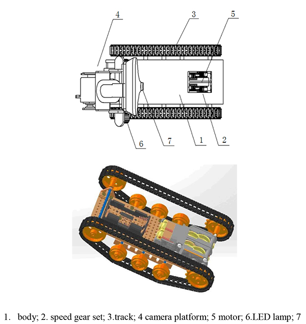 ), the mechanical structure of the robot mainly includes the power source 5, the gear set transmission mechanism 2, the crawler moving mechanism 3, servo mechanism 4, robot hand mechanism (mounted on the casing 1), LED lights 6, camera 7 and other components.
 |
Fig. (2) Mechanical structure of the robot. |
3.1. Power Source
DC motor as the power source has fine drive ratio that makes speed adjustment easier to find a perfect speed to coordinate with the camera video acquisition and WiFi transmission speeds [4E.A. Ramadan, M. El-Bardini, and M.A. Fkirin, "Design and FPGA-implementation of an improved adaptive fuzzy logic controller for dc motor speed control", Ain Shams Eng. J., vol. 5, no. 3, pp. 803-816, 2014.
[http://dx.doi.org/10.1016/j.asej.2014.04.002] ]. It is in small size with compact structure and strong ability to withstand overloads, which satisfies the requirements for a robot to work in a narrow and harsh environment. The equipment is in new type with good protection performance for continuous working in corrosive, damp and other harsh environment.
3.2. Design of the Transmission Gear Set and Crawler Mobile Unit
By using differential crawler movement manner [5B. Maclaurin, "A skid steering model using the magic formula", J. Terramechs., vol. 48, no. 4, pp. 247-263, 2011.
[http://dx.doi.org/10.1016/j.jterra.2011.04.002] ], the left and right tracks are respectively controlled by wheels driven by two motors, and each wheel is connected to the robot body via a spring damping device. Since the space under a vehicle is very limited, in order to efficiently detect the vehicle chassis, the robot must be able to perform flexible steering with small turning radius. Differential crawler movement manner is advantageous in flexible movement and convenient control, which can help complete situ rotation and other difficult manoeuvre. It can adapt to various workplaces and maintain the highest stability in a complex space, providing the basis for collecting stable chassis videos at the mean time of running. When the robot runs too fast, the image quality might be poor due to performance of the camera and WiFi transmission efficiency, leading to poor detection results. While using the PWM control motor, there might be a driving force shortage when the motor speed is below a certain threshold, leading to poor obstacle climbing performance. Therefore, a mechanical gear set (Fig. 3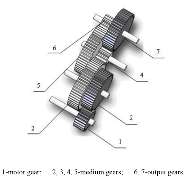 ) has been used to slow down the motor.
 |
Fig. (3) The gear set of the robot mobile system. |
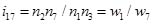
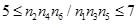
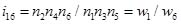
According to the design requirements, the gear set transmission ratio should be between 1/7 to 1/5. Limited by the structure of the robot, a set of gears as shown in Fig. (3) have been designed, where the gears 4/5/6/7 satisfy the features of concentric gear wheel system:
 |
(1) |
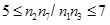
Experiments showed that the robot performance is better when the speed gear ratio is between 5 and 7, namely:
 |
(2) |
 |
(3) |
 |
(4) |
 |
(5) |
The motor rotational speed is stabilized at 500rpm using PWM control, and then adjusted to 85rpm using this speed gear set. Practice has proven that the robot with this gear set is stable and robust and is capable to overcome the problem of insufficient power at low speeds.
3.3. Design of the Camera Platform
Two servo motors controlled by SCM are used to drive the camera platform, powered by a servo module that drives the two independent rotating surfaces arranged perpendicular to each other. Scroll bars of the platform control variation of the two servo angles of the two independent perpendicular rotation planes, so that one motor drives camera in a horizontal plane and the other drives in the vertical plane. The camera is mounted on the top of the platform and the orientation can be freely adjusted, providing an unrestricted field of vision to complete a full range of chassis detection.
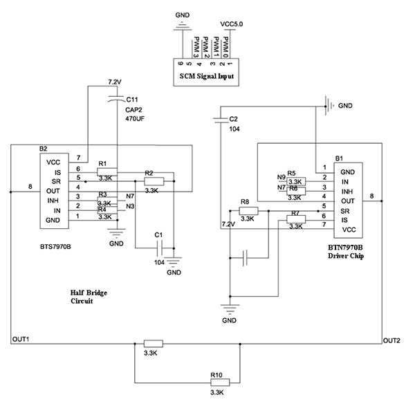 |
Fig. (4) Portion of the motor drive control circuit. |
4. DESIGN OF THE ELECTRONIC CIRCUIT
The overall performance of the robot depends on its regulated power supply system and the motor drive system [6S.T. West, B.A. Welchko, S.E. Schulz, and S. Hiti, "Phase current sampling and regulating apparatus and methods, and electric motor drive systems", US, US7834574, 2010.]. The drive system generally consists of three main parts namely the system controller, power controller and working electrodes [7F.O. Societies, "Simulation modelling practice and theory", Simul. Model. Pract. Theory, vol. 16, no. 8, pp. 933-944, 2008.]. Robot drive requires not only the motor drive system with high torque, speed range, stable performance, but also stable motor torque - speed characteristics. DC servo motor control is simple with superior performance and easy implementation, which provided basis for the design of the drive system and the power regulation circuits.
4.1. Motor Drive Circuit
The motor is driven by an H-bridge circuit that was built upon two BTN7971 chips in a simple design, requiring only one PWM control channel [8M.B. Ahrens, J.M. Li, M.B. Orger, D.N. Robson, A.F. Schier, F. Engert, and R. Portugues, "Brain-wide neuronal dynamics during motor adaptation in zebrafish", Nature, vol. 485, no. 7399, pp. 471-477, 2012.
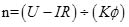
[PMID: 22622571] ], 2012). The on-chip power consumption is relatively small, leading to low heat and stable performance, so that the affection by the power heat can be effectively avoided. The direction of motor current can be controlled, providing advantageous performance for emergency stop and quick start. The motor output is given by
 |
(6) |
In the above equation, n is the rotational speed of the DC motor, U is the armature voltage, I is the armature current, R is the total resistance of the armature, φ is the magnetic flux, K is structural parameters of the motor. This formula indicates that motor speed can be controlled by the excitation magnetic flux or armature voltage. The equivalent armature voltage control method is adopted based on PWM waves for DC motor speed adjustment.
 |
(7) |
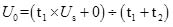
The PWM control intends to change the duty cycle of a square wave signal, i.e. the conduction time t1 during a cycle, when the supply voltage Us is constant. In this case, Uo is the equivalent armature winding terminal voltage of the motor, D is the duty cycle representing the conduction time period ratio in a cycle (0≤D≤1). Portion of the driving circuit is shown in Fig. (4 ).
).
4.2. Design of the Stabilized Power Supply Circuit
Automobile chassis inspection robot requires stable power supply, for which reason three-terminal regulator chips are adopted to construct a simple circuit (Fig. 5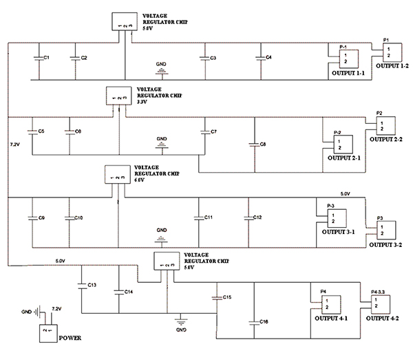 ). Capacitors were used between input/output voltages of the chips and the ground, which filters out the current fluctuations with workloads and improves the power stability.
 |
Fig. (5) Stabilized power supply circuit. |
4.3. WiFi Communication
The WiFi communication relies on a TP-LINK WR703N wireless router, which has been updated with OpenWrt firmware to make the router work like a small Linux system, adaptive to privately developed driver software [9M. Jingli, and L. Teng, "Design of smart home server based on openwrt", Network Security Technol. and Appl., vol. 11, pp. 197-198, 2014.]. Through modification, TX / RX serial communication was added, using which the router system and drive software can be re-written. After the corresponding camera driver was installed, video images can be captured via a USB camera. Meanwhile the communication protocol was updated after modification via serial ports [10V.S. Malladi, A. Mishra, and Z. Ji, "System and method of determining a location based on location of detected signals", US, US 8150367 B1, 2012.], so that two-way real-time transmission of video data and control data can be completed simultaneously.
5. DESIGN OF THE CONTROL SYSTEM SOFTWARE
5.2. Interface of the Control Platform
The control platform is developed into exe software running on the remote computer, which consists of menu bar, video display area, control buttons and slid bars as shown in Fig. (7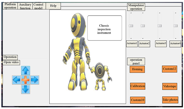 ):
):
The platform client terminal exchanges data with the robot routing module via TCP/IP communication protocol. The control platform can call the robot camera to obtain images in real time, with saving and playback functions [11N.T. Luy, N.T. Thanh, and H.M. Tri, "Reinforcement learning-based intelligent tracking control for wheeled mobile robot", Trans. Inst. Meas. Contr., vol. 36, no. 7, pp. 868-877, 2014.
[http://dx.doi.org/10.1177/0142331213509828] ]. The communication protocol is stored in the robot system control platform. After successful logging into the control platform via WiFi router, a new thread immediately starts, waiting for control platform to issue control instructions. The microcontroller system responds after the instructions are received.
 |
Fig. (7) Control platform diagram. |
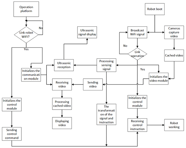
5.3. Robot Workflow
The robot workflow is as shown in Fig. (6 ).
).
- The robot powers on, the WiFi routing communication module starts broadcasting WiFi signals, and waits for the robot control platform to build connection and control.
- Run the control platform, search for and connect to the robot via WiFi.
- The control platform confirms WiFi connection is completed, and prompts to select the control mode. Initialization of each module is completed, and the vehicle chassis inspection robot finishes preparation works.
- Control the robot to move back and forth or left to right via the WSAD four-button keypad or arrow keys on the control platform. It is then possible to control the orientation of the camera platform and the robot hand to perform corresponding actions by dragging the slide bars in the control platform.
- The vehicle chassis inspection robot can automatically run along with designed routes and collect video images at a certain site, and transmit the videos to the control platform via WiFi for storage. It is also possible to artificially control the robot, perform visual check of vehicle chassis at a specific position. The inspection status is as shown in Fig. (8
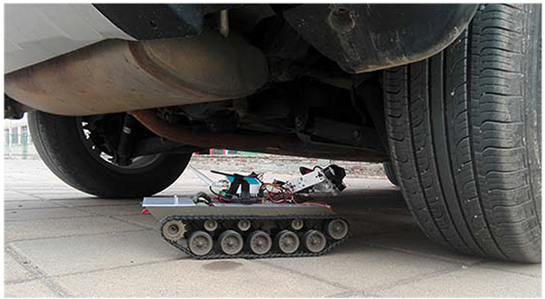 ).
).
 |
Fig. (8) The inspection status of the robot. |
6. EXPERIMENTS
Experiment is an essential part of the robot design process, and it took eight months from the initial experiment of simple moving to completion of the overall system design.
6.1. The Robot Moving and Camera Stability Experiments
When the robot has just completed structures, many disadvantages in structural design started to emerge, leading to unstable operation. The camera coordinates with the entire system in an imperfect manner, often jams, while the videos are sometimes discontinuous. It was found that the root problem is that the transmission structure is somehow irrational and the movement is unstable. The robot has then been revised according to the test results in varying environment.
During experiments, the robot was driven with categorized speed ranges for different road conditions, including a flat concrete floor, a road with different degrees of potholes, roads with different slopes. It was found that the motor speed limit when running on a flat road surface is 115rpm and the camera collected images exhibit jam phenomenon when the speed is above this limit. For the road with potholes, the video jitters seriously when the speed is more than 98rpm, which cannot satisfy the chassis inspection purposes. On the uphill sections, the drive motor stops working when the speed is below 48rpm, and the optimum speed is between 58rpm and 125rpm. According to these experimental results and comprehensive analysis, a gear set has been designed to provide better speed performance.
6.2. Comprehensive Evaluation of the Robot
Some video screenshots captured by the robot are shown in Fig. (9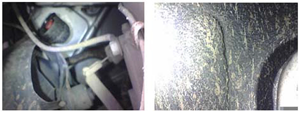 ).
).
 |
Fig. (9) Image captured by the chassis inspection robot. |
As shown above, the vehicle chassis inspection robot can provide results that satisfy the requirements of the automotive service industry, fully meet the design objectives. During automatic inspection, the influence of light intensity on the robot detection results is given below Table 1
Experimental results showed that, between 8:30am and 16:30pm, 96% area of the car chassis can be clearly observed by the robot, which means that the robot can be operated in full order to provide good detection results.
The Table 2 shows how different routes affect time spent on inspection.

When S route as shown in Fig. (10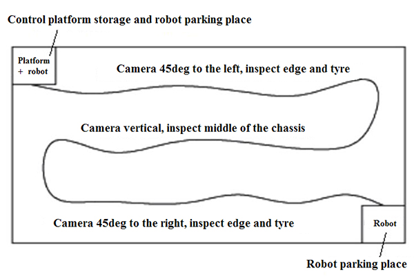 ) is used for chassis inspection, the vehicle chassis including inner surface of the tires can be fully detected without dead vision space, leading to good results and high efficiency. After comparison with the data collected from vehicle service companies, it was found that 40% inspection time can be saved after using this robot.
 |
Fig. (10) Robot working site and route. |
7. SUMMARY
- This study investigated transmission structures of an automobile chassis inspection robot and analyzed the detection results, designed a camera servo platform head and a robot arm.
- Control command data and video images are synchronously transmitted using WiFi network technology.
- Under VS environment, the control platform of the robot has been developed using C # language.
- This design achieves full inspection of vehicle chassis without the need of using lifting device to raise the vehicles. It saves 40% of the inspection time for each vehicle, reduces energy consumption during detection so as to reduce costs, and reduces risk factor of employees.
HUMAN AND ANIMAL RIGHTS
No Animals/Humans were used for studies that are base of this research.
CONSENT FOR PUBLICATION
Not applicable.
CONFLICT OF INTEREST
The authors declare no conflict of interest, financial or otherwise.
ACKNOWLEDGEMENTS
This project is founded by Shandong Province special funding to upgrade technology research of large scientific instruments (ID: 2013SJGZ26) and the Scientifc Research Fund of Liaocheng University, China. (Grant no. 318011519).
REFERENCES
| [1] | W. Tianmiao, T. Yong, and C. Yang, "Research status and development trends of the service robotic technology", Scientia Sin. Inf., vol. 9, no. 42, pp. 1049-1066, 2012. |
| [2] | Z. Ran, L. Yanwen, and Z. Tieshi, "Present situation of researches and trend of development of micro-robots", J. Mach. Design, vol. 26, no. 2, pp. 1-2, 2009. |
| [3] | H.W. Tsai, C.P. Chu, and T.S. Chen, "Mobile object tracking in wireless sensor networks", Comput. Commun., vol. 30, no. 8, pp. 1811-1825, 2007. [http://dx.doi.org/10.1016/j.comcom.2007.02.018] |
| [4] | E.A. Ramadan, M. El-Bardini, and M.A. Fkirin, "Design and FPGA-implementation of an improved adaptive fuzzy logic controller for dc motor speed control", Ain Shams Eng. J., vol. 5, no. 3, pp. 803-816, 2014. [http://dx.doi.org/10.1016/j.asej.2014.04.002] |
| [5] | B. Maclaurin, "A skid steering model using the magic formula", J. Terramechs., vol. 48, no. 4, pp. 247-263, 2011. [http://dx.doi.org/10.1016/j.jterra.2011.04.002] |
| [6] | S.T. West, B.A. Welchko, S.E. Schulz, and S. Hiti, "Phase current sampling and regulating apparatus and methods, and electric motor drive systems", US, US7834574, 2010. |
| [7] | F.O. Societies, "Simulation modelling practice and theory", Simul. Model. Pract. Theory, vol. 16, no. 8, pp. 933-944, 2008. |
| [8] | M.B. Ahrens, J.M. Li, M.B. Orger, D.N. Robson, A.F. Schier, F. Engert, and R. Portugues, "Brain-wide neuronal dynamics during motor adaptation in zebrafish", Nature, vol. 485, no. 7399, pp. 471-477, 2012. [PMID: 22622571] |
| [9] | M. Jingli, and L. Teng, "Design of smart home server based on openwrt", Network Security Technol. and Appl., vol. 11, pp. 197-198, 2014. |
| [10] | V.S. Malladi, A. Mishra, and Z. Ji, "System and method of determining a location based on location of detected signals", US, US 8150367 B1, 2012. |
| [11] | N.T. Luy, N.T. Thanh, and H.M. Tri, "Reinforcement learning-based intelligent tracking control for wheeled mobile robot", Trans. Inst. Meas. Contr., vol. 36, no. 7, pp. 868-877, 2014. [http://dx.doi.org/10.1177/0142331213509828] |