- Home
- About Journals
-
Information for Authors/ReviewersEditorial Policies
Publication Fee
Publication Cycle - Process Flowchart
Online Manuscript Submission and Tracking System
Publishing Ethics and Rectitude
Authorship
Author Benefits
Reviewer Guidelines
Guest Editor Guidelines
Peer Review Workflow
Quick Track Option
Copyediting Services
Bentham Open Membership
Bentham Open Advisory Board
Archiving Policies
Fabricating and Stating False Information
Post Publication Discussions and Corrections
Editorial Management
Advertise With Us
Funding Agencies
Rate List
Kudos
General FAQs
Special Fee Waivers and Discounts
- Contact
- Help
- About Us
- Search


The Open Fuels & Energy Science Journal
(Discontinued)
ISSN: 1876-973X ― Volume 11, 2018
Study on the Vibration Response Characteristics of Broken Roof Rock in Coal Roadway
Shuying Guo1, 2, *
Abstract
Background:
Aiming at the challenges in control and perdition of roof strata which caused by the complexity of coal mine roof, the force and vibration characteristics of drill bit have been analyzed considering the coupling vibration between drill bit and coal rock, and the characteristics of coupled vibration have been studied under the condition of different rock hardness.
Methods:
The least-square method has been used to fit the vibration curve, besides, the trend term has been eliminated, and smooth treatment has been processed on the curve as well.
Results:
The study shows that the transverse vibration radius of the drilling mechanism increases as the coal rock hardness amplifies under the same experiment condition, and for same type rock, the horizontal vibrating decreases with the increase of fracturing intensity.
Conclusion:
The result shows that in anchor hole of coal roadway, the broken zone can be judged, and the degree of rock failure hazard can be predicted. Besides, the position and thickness of the stable rock in the anchor hole can also be judged, and technical support for roof support design can be provided.
Article Information

Identifiers and Pagination:
Year: 2016Volume: 9
First Page: 92
Last Page: 101
Publisher Id: TOEFJ-9-92
DOI: 10.2174/1876973X01609010092
Article History:
Received Date: 18/12/2015Revision Received Date: 29/09/2016
Acceptance Date: 18/10/2016
Electronic publication date: 17/11/2016
Collection year: 2016
open-access license: This is an open access article licensed under the terms of the Creative Commons Attribution-Non-Commercial 4.0 International Public License (CC BY-NC 4.0) (https://creativecommons.org/licenses/by-nc/4.0/legalcode), which permits unrestricted, non-commercial use, distribution and reproduction in any medium, provided the work is properly cited.
* Address correspondence to this author at the Faculty of Resource and Safety Engineering, China University of Mining and Technology(Beijing), Ding on the 11th, Xueyuan Road, Haidian District, Beijing, 100083, China; Tel/Fax: 13321181159; E-mail:syg2007@126.com
| Open Peer Review Details | |||
|---|---|---|---|
| Manuscript submitted on 18-12-2015 |
Original Manuscript | Study on the Vibration Response Characteristics of Broken Roof Rock in Coal Roadway | |
1. INTRODUCTION
According to some investigations, most of roof falling accidents in coal roadway happen in those geological areas where there are weak interlayers, small roof faults, anterior implicit faults or joints and leaks. These poor geological changes may break the integrity of coal roadway roof and cause the broken areas, which become the main reason of the roof falling accidents. Ever since the geological structural scales of broken areas are small and elusive, it is difficult to find reliable ways to detect its exact positions and ranges before supporting, which is employed to predict whether or not there will be a roof falling. Currently, the fractured zone measuring has always been adopted to detect broken areas of roadway roof, which may include ultrasonic method, multipoint displacement, resistivity, geological ground penetrating radar method and so on. Among them, most widely used is ultrasonic testing method, which is mature and has simple principle. But when carrying out the tests at the scene, it is found that the actual operation is very difficult and the testing results are quite different from the actual situation since water is used as the coupling media, which calls for enormous demands for water pressure, water flow and water quality [1Yigit, A.S.; Christoforou, A.P. Coupled torsional and bending vibrations of drillstrings subject to impact with friction. J. Sound Vibrat., 1998, 215(1), 167-181.
[http://dx.doi.org/10.1006/jsvi.1998.1617] -8Hou, C.J. Ground Control of Roadways; China University of Mining & Technology Press: Xuzhou, 2013, pp. 186-194. M]. Besides, the fractured zone measuring is always carried out in drilled holes, thus the holes should be drilled in advance, which demands not only extra workload, but also extra time.
Therefore, this paper focuses on the coupling vibration between drilling mechanism and coal roadway roof, meaning to find out the broken zone and its range, to provide a reference for detecting the roof falling hazard, and to provide better techniques for roadway support.
2. INFLUENCE OF ROCK MASS MECHANICS PERFORMANCE ON VIBRATION CHARACTERISTICS OF BOLTER IN COAL ROADWAY
In the process of bolter drilling, the rig bit is forced into the rock under the axial force and cuts the rock under the rotary torque. Thus, frication occurs when rig bit is moving on the surface of the rock, and roof rock mass is affected comprehensively by pressure, frication and cutting force of the rig bit. The rock is destroyed and cut down when the stress is larger than failure strength, and holes are formed after the roof is destroyed by the rig bit. Therefore, the efficiency of drilling mechanism is influenced by dead weight, forward resistance and frication when the rig bit drills roadway roof. The forward resistance and frication are related to the physical and mechanical properties of roof strata, such as density, strength, cohesion, hardness and so on [9Liu, H.T.; Ma, N.J. Coal mine roadway roof caving high risk areas recognition technology. J. China Coal Soc., 2011, 36(12), 2043-2047.-11Liu, H.T.; Zhao, Z.Q.; Fan, L. The relationship between roof shallow crack channel and drilling signals. J. China Coal Soc., 2013, 6, 954-959.]. Studies have shown that the comprehensive affection of drilling mechanism is closely related to the features of drilling rig. On the one hand, the larger the comprehensive affection is, the more obvious of vibration performance of drilling rig will be, so the bigger power of drilling rig will be needed. On the other hand, the smaller of the comprehensive affection is, the more stable of the drilling vibration performance will be.
3. STRESS ANALYSIS OF BOLTER BIT
It has a significant impact on vibration performance of drilling rig that the physical and mechanical properties of roof rock mass material. The vibration performance of drilling rig is obvious when the parameter of drilling rig is identical and the strength or hardness of roof rock mass is quite large, and the vibration performance is not obvious on the contrary. The vibration performance is also greatly influenced by the stress of rig bit when jumbolter is drilling. Therefore, the stress of jumbolter bit will be analyzed in the following section.
3.1. Stress Analysis of Jumbolter Bit
The jumbolter bit is to apply stress to the contact surface of the rock, at the same time, it applies the torque around the axis to drive the drill to rotate and cut the rock. It is the rock breaking process. In this process, there are two kinds of movements of broken rocks, one is the axial movement to break the core of the, and the other is the rotating broken movement around the core. With these two movements, the jumbolter bit goes along with the spiral trajectory to make drill holes. In rock breaking, drill bit is forced by the drilling rig, at the same time, the surface is also affected by the resistance of the rock, which is generated by elastic and plastic deformation and the resistance is related to the strength of rock. These forces are superimposed together, forming the total drilling force of the jumbolter bit, and under the influence of total drilling force, a spiral upward movement of the bolt drill will be formed [12Jia, M.K. A new way of genetic classification on roof falling of bolt supporting roadway. J. China Coal Soc., 2005, 30(5), 568-570.-16Liu, S.W.; Feng, Y.L.; Liu, D.L. Numerical experiments of dynamic response characteristics of rock drilling on stratified roof in coal roadway. Chinese J. Rock Mech. Eng., 2014, 1, 3170-3175.].
3.2. Analysis of Vibration Characteristics of Drill Bit
In the process of the drilling roof of coal roadway, the drill holes are mainly caused by the axial vibration of the drill bit and the crushing effect of cutting. The basic assumption of the whole drilling mechanism dynamics model is as follows. Firstly, screw rod is a homogeneous rod; secondly, the axis of the drilling mechanism is coincident with the borehole axis; thirdly, the input rotation speed of the screw rod does not change with time; fourthly, the lateral vibration of drill bit is decomposed into two directions, X and Y.
The drilling system is highly nonlinear, and there is friction between the drill rob and coal rock, so even an analytical solution is not found in the continuous drill rob system. According to the finite element method [17Chen, Y.; Liu, P. Dynamic study on drilling unit of auger shearer. Minds Mach., 2013, 41(10), 13-17.], the vibration equation of the whole drilling mechanism has been analyzed.
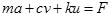 |
(1) |
In Eq.(1), m is the drilling mechanism of the whole unit mass matrix; c is the drilling mechanism of all element damping matrix; k is the drilling mechanism of whole unit stiffness matrix; a is the overall acceleration of screw drill rod; v is the overall speed of screw drill rod; u is the overall displacement vector of screw drill rod; and F is the drilling structure equivalent external load vector.
By using the Houbolt method, the system dynamics equation is solved as follow:
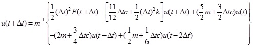 |
(2) |
In Eq.(2), t is the test time of the drilling structure, Δt is the test interval of the drilling structure, u(+Δt) is the overall displacement vector of screw drill rod at t+Δt moment, u(t) is the overall displacement vector of screw drill rod at t moment, u(t-Δt) is the overall displacement vector of screw drill rod at t-Δt moment, u(t-2Δt) is the overall displacement vector of screw drill rod at t-2Δt moment, F(t+Δt) is the drilling structure equivalent external load vector at t+Δt moment.
According to the relevant literature and field experience, the axial force and tangential force of the drill bit have the most influential effect on the vibration characteristics of the drilling machine. In the processes of drilling the holes into rock and broken rock respectively, since the physical and mechanical properties of rocks are different, the axial force and tangential force of the drill bit are also different. It is obvious that the different vibration characteristics of the jumbolter in different rock strata. At the same time, since the vibration signal is more easy to obtain than other signals, the method of using vibration signal for rock strata identification is closer to the artificial judgment. Therefore, the roof lithology can be identified by researching the different vibration characteristics of drilling holes.
4. EXPERIMENTAL STUDY ON ROOF BOLTER DRILLING
In the process of drilling, due to the changing of drilling objects, roof bolter anchor drag torque, radial and rotational torque effect change as well and these changes work directly on drill rigs in the form of forces, its excitation will generate vibration response of bolter. If the direct relationship between the vibration signal and the working state of roof bolter was found, then we can work through the vibration signal to determine the working state of the bolt rig, so as to achieve integrated rock state and broken rock formations recognition. Due to some constraints, this paper simplifies the actual structure of the roof bolter, and builds the bolt rig drilling model to test the feasibility of applying the vibration signal recognition roof strata properties in the laboratory.
4.1. Selection of the Test Material
Physical and mechanical properties of the rock have a great impact on bolt rig working state, energy drilling, drill forces and so on; therefore, the selection of the analog material should be determined through the analysis. Based on Jinjie mining field roof rock, the test material has been selected. The seam lithology of roof rock is gray and black, dark gray sandy shale, mudstone, sandstone coarse gray fine-grained sandstone, limestone and siltstone. The true density of the rock is 2062 ~ 3225kg / m3, compressive strength is 3.36 ~ 40MPa in water status, and the average is 13.98MPa, it is 1.6 ~ 51.5MPa in the natural state, the average is 21.80MPa, Platt coefficient is from 0.17 to 5.41, shear strength is from 1.5 to 26.6MPa, 26 ° 04 '~ 40 ° 21' of internal friction angle, 4.98 ~ 8.04GPa of Elastic modulus, 0.07 ~ 0.56 of Poisson's ratio, 0.90 ~ 5.28 of Mpa Tensile strength.
The test material come from Jinjie mine, and the four kinds of hardness of the test material are f = 4.2, f = 3.5, f = 2.55, f = 2 all of which has the same kind of overburden strata crushing body, thus taking them as the drilling objects to test the drill vibration performance.
4.2. Design of the Test Program
By analyzing the working principle of identification methods of the roof failure, the signal acquisition and processing methods are determined. The basic principle of signal acquisition is to observe rock as the research object, and simulate the actual operating status and the status of anchor drilling rig, and complete the acquisition of vibration signals, choosing the appropriate signal processing methods for vibration analysis of the test data to achieve the goal of identifying the roof failure.
The previous researches show that when the bolt rig works, the vibration characteristics of the drill bit of the work can effectively reflect the working state of roof bolter. So the acceleration vibration sensor should be installed at the bottom of the drill rig anchor, and vibration sensor should be connected with a threaded connection, and be installed between the rig and drill and adopting self-developed data collection instrument for vibration signal acquisition and processing.
4.3. Vibration Signal Processing
In the process of signal acquisition, there is a disturbance in the test system, and the vibration sensor will be zero offset with the change of temperature. So, there are a lot of noise and interference in the data acquired by the sensor and data acquisition system, leading to the deviation of the data from the baseline, so in order to ensure the correctness of the data, the data must be processed to eliminate the noise and interference in the sampled data. The elimination of the trend can be modified due to the deviation of the sampling data caused by the distortion of the distortion. Smooth processing can eliminate the noise and interference in the sampled data. The elimination of the trend term and smoothing the data can effectively reduce the interference of noise to the signal and improve the noise ratio
4.3.1. Elimination Trend Term
Through theoretical analysis and experimental verification, in the vibration signal measurement, the vibration effect disappears, and the signal is changed by the polynomial decay law. Thus, the trend of the signal is determined by polynomial trend term. In this paper, the least square method is used to fit the acceleration baseline [18Cui, C.X.; Tan, C.J. Coupling vibration of a drilling system with interaction between drilling mechanism and coal rock. J. Vib. Shock, 2014, 16, 97-103., 19Wang, Y.; Xue, Y.C.; Ma, T.H. Research on zero drift processing method using EMD and least-square. Trans. Beijing Inst. Technol., 2015, 2, 118-122.], and eliminate the polynomial trend term. According to the principles that the values of signal sample on both sides of average line need to be evenly distributed and polynomial number should be as low as possible, the polynomial simulation degree is considered to be good by comparing the different orders of the integral displacement with the mean baseline, the measured vibration signal of the test system is obtained based on the interval of Δt {Xi}(i = 1,2,3,…,n), if Δt = 1, according to the characteristics of the polynomial trend, it is the linear term, and the model can be described as:
 |
(3) |
In Eq.(3), xi is the polynomial trend term, a0 and a1 are the model parameters, that is, to be solved coefficient, i is the sequence number of the measured vibration signal, n is the number of the measured vibration signal.
According to the principle of least square method, making the sampling data Xi and xi the function of the error square and minimum, E is the error function expressed as:
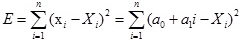 |
(4) |
Where E is the error function, Xi is the measured vibration signal.
For error function E find out minimum value, in order for a0 , a1 working out partial derivative, so
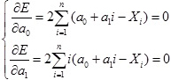 |
(5) |
Where
 is the partial derivative of a0 for error function E,
 is the partial derivative of a1 for error function E.
The linear equations of the trend term are listed in the formula (5), and the solution is to be solved.
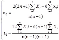 |
(6) |
Where a0 and a1 are the coefficient of the trend term function.
The formula for eliminating the trend term of vibration signals is:
 |
(7) |
Where Yi is the vibration signal of item i(i = 1,2,3,…,n) after eliminating trend term, n is the number of data points.
Coal and rock hardness of test preparation are f=4.2, f=3.5, f=2.55, f=2 respectively and all of which have the same kind of overburden strata crushing body. Fig. (1) shows the oscillogram of vibration radius-drilling depth of integrated and broken rock with different hardness, which is cut by drilling mechanism.
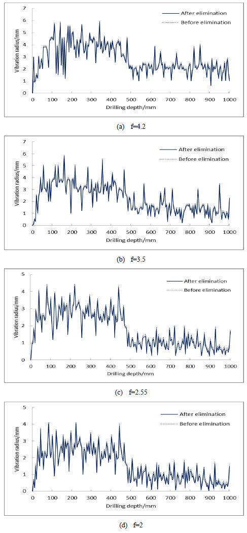 |
Fig. (1) Vibration radius and depth wave of drilling rock after eliminating trend term. |
4.3.2. Smooth Processing of Sampled Data
Due to the data collected by the acquisition system which contains periodic noise and irregular random interference signal, there are many glitches and spikes on the plotted curves of the sampling data. In order to eliminate and weaken the influence of the interference and to improve the smoothness of the sampled data, it is necessary to smooth the sampling data. There are kinds of smoothing methods, such as, average method, Good - Turin smoothing method, Laplacian smoothing method, five point three times smoothing method, etc., of which five point three times smoothing method is very easy, it can reduce the high frequency noise in the input signal and makes the signal smooth, and it has good fitting effect in the parameter identification. So in this paper, the method of least square method is adopted to process the sampled data for five point three times smoothing method [20Hu, C.Y.; Chen, Q.J. Research on base line drift using least-square and EMD. J. Vib. Shock, 2010, 29(3), 162-167.-22Zhu, C.C.; Song, C.S.; Wang, Q.F. Nonlinear stability analysis for helical buckling of drill string in well bore. J. Southwest Pet. Univ. (Sci. Technol. Ed.), 2010, 32(2), 1159-1163.]. The smoothing method can reduce the interference components in the input signal, and can keep the invariant data characteristics of the curve.
The data on the 2N+1 are respectively: X-n, X-n+1,…,X-1, X0 , X1,…,Xn-1, Xn, using m sub polynomial fitting sampling data, m refers to the number of data points. Fitting function
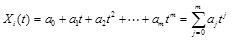 |
(8) |
Where Xi(t) is the fitting function, ak(k = 0,1,2,…,m) are the coefficient for the solution to be solved, m is the number of data points.
The least square method is used to solve the undetermined coefficient. So
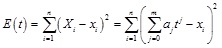 |
(9) |
Where E(t) is the error function.
For error function E(t) finds out minimum value, in order to work out ak(k = 0,1,2,…,m) partial derivative, the equations are listed in the formula (10), so
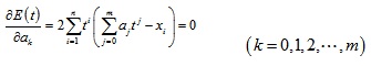 |
(10) |
Where
 is the partial derivative of ak(k = 0,1,2,…,m) for error function E(t).
When n=5(5points), m=3, the solution is to be solved. ak(k = 0,1,2,…,m) plugged into formulas (8), so
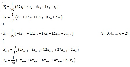 |
(11) |
In Eq.(11), Y1 is the 1st vibration signal after smoothing, Y2 is the 2nd vibration signal after smoothing, Yi is the vibration signal of item i(i = 3,4,…,m-2) after smoothing, Ym-1 is the vibration signal of item m-1 after smoothing, Ym is the vibration signal of item m after smoothing, m is the number of data points.
Data smoothing has been carried out by using five point three times smoothing method, the wave of vibration radius and depth in drilling different hardness of integrated and broken rock is shown in Fig. (2).
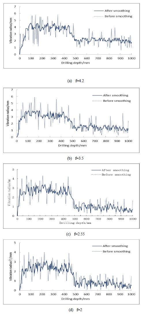 |
Fig. (2) Vibration radius and depth wave of drilling rock after smoothing treatment. |
4.4. Test Result Analysis
In Fig. (2a), a sudden change occurs to the curve in drilling depth of 500mm or so. In Table 1, the average vibration radius decreases in the range of 0-500mm and 500-1000mm, which indicates that vibration amplitude shows an obvious trend of decrease. Standard deviation can be used to measure fluctuation characteristics of the curve, the bigger the value is, the bigger the fluctuations is. In these two ranges, the standard deviations are 0.41 and 0.24 respectively, which show that the drilling mechanism vibration in the range of 500-1000mm changes more slowly than that in the range of 0-500mm.
Measured parameters under the condition of f=3.5 are shown in Table 2. The average radii are 3.18 mm and 1.38 mm, respectively in the ranges of 0-500mm and 500-1000mm. The vibration amplitude shows an obvious trend of decrease. In these two ranges, the standard deviations are 0.44 and 0.28, respectively, which indicate that the drilling mechanism vibration in the range of 500-1000mm changes more slowly than that in the range of 0-500mm.

Measured parameters under the condition of f=2.55 are shown in Table 3. Table 3 and Fig. (1c) show that in the ranges of 0-500mm and 500-1000mm, the average radii are 2.69 mm and 0.85 mm, respectively. The vibration amplitude shows an obvious trend of decrease. In these two ranges, the standard deviations are 0.39 and 0.29, respectively, which indicate that the drilling mechanism vibration in the range of 500-1000mm changes more slowly than that in the range of 0-500mm.

Measured parameters under the condition of f=2 are shown in Table 4. Table 4 and Fig. (1d) show that in the ranges of 0-500mm and 500-1000mm under the condition of f=2, the average radiuses are 2.38 mm and 0.69 mm, respectively. The vibration amplitude shows an obvious trend of decrease. In these two ranges, the standard deviations are 0.36 and 0.28 respectively, which indicate that the drilling mechanism vibration in the range of 500-1000mm changes more slowly than that in the range of 0-500mm.

In order to investigate the impact of integrated and broken rock on transverse vibration properties of drilling mechanism, the results of Fig. (1) and Tables 1-4 are compared and analyzed. It is shown that vibration radius of drilling mechanism increases with the increase of coal and rock hardness, and the vibration radius of drilling mechanism differs greatly when cutting integrated rock and broken rock with different hardness, and the former changes are more obviously than the latter ones.
CONCLUSION
(1) Through analyzing the stress profile and the vibration characteristics of boring rod during the coal (rock) boring process, the coupling characteristics of transverse vibration of boring tool is defined.
(2) As boring with the jumbolter, unstable transverse vibration of boring rod occurs due to the anisotropism-induced frictional resistance difference. With the decrease of coal (rock) hardness, the corresponding frictional resistance boring rod beard is changing downward, then the transverse vibration due to friction is weakened.
(3) The experimental results for coal (rock) boring test with various hardness indicate that the amplitude of poring rob is increasing with the growing hardness of coal (hard); under the same test condition and with the same hardness, poring within fractured coal (rock) mass will cause relatively smaller amplitude and this downward trend is continuing with the increasing fracture development degree.
(4) Based on different vibration response of boring rob for coal (rock) with various fracture development degree, the broken range around the underground mining roadways can be determined and described during the boring process, and the further prediction of roof falling risk can be made. In addition, the vibration log of boring rod will report the layer characteristic along the boring hole, such as the density, heights and stability, which are the basis for roadway support design.
CONFLICT OF INTEREST
The author confirms that this article content has no conflict of interest.
ACKNOWLEDGEMENTS
This work is supported by the National Natural Science Foundation of China (No.51234005) and the National Basic Research Program of China (973 Program) (No. 2011CB201204)
REFERENCES
| [1] | Yigit, A.S.; Christoforou, A.P. Coupled torsional and bending vibrations of drillstrings subject to impact with friction. J. Sound Vibrat., 1998, 215(1), 167-181. [http://dx.doi.org/10.1006/jsvi.1998.1617] |
| [2] | Khulief, Y.A.; Al-Sulaiman, F.A.; Bashmal, S. Vibration analysis of drill strings with self-excited stick-slip oscillations. J. Sound Vibrat., 2007, 299(3), 540-558. [http://dx.doi.org/10.1016/j.jsv.2006.06.065] |
| [3] | Qian, M.G.; Xu, J.L. Study on the “O shape” circle distribution characteristics of mining induced fractures in the overlaying strata. J. China Coal Soc., 1998, 23(5), 466-469. |
| [4] | Lin, Y.H.; Shi, T.H.; Li, R.F.; Zeng, D.; Liu, X.; Zhang, D. Simulation of impact force and penetration rate of air hammer bit drilling. Chinese. J. Rock Mech. Eng., 2005, 24(18), 3337-3341. |
| [5] | Liu, J.L.; Zhao, H.J.; Li, C.Y. Coal-Rock recognition method based on cutting vibration features of coal shearer drums. Coal Sci. Technol., 2012, 10, 93-95. |
| [6] | Zhu, X.H.; Luo, H.; Jia, Y.J. Numerical analysis of air hammer bit drilling based on rock fatigue model. Chinese J. Rock Mech. Eng., 2012, 31(4), 754-761. |
| [7] | Li, Q.F.; Zhu, C.Q.; Duan, Y. The numerical simulation of prestress rockbolt supporting system dynamical characteristics. J. China Coal Soc., 2008, 33(7), 727-731. |
| [8] | Hou, C.J. Ground Control of Roadways; China University of Mining & Technology Press: Xuzhou, 2013, pp. 186-194. M |
| [9] | Liu, H.T.; Ma, N.J. Coal mine roadway roof caving high risk areas recognition technology. J. China Coal Soc., 2011, 36(12), 2043-2047. |
| [10] | Ma, D.K. Mutual actions between rock and nit and wellborn deviation. J. Southwest Pet. Inst., 1983, 5(3), 51-58. |
| [11] | Liu, H.T.; Zhao, Z.Q.; Fan, L. The relationship between roof shallow crack channel and drilling signals. J. China Coal Soc., 2013, 6, 954-959. |
| [12] | Jia, M.K. A new way of genetic classification on roof falling of bolt supporting roadway. J. China Coal Soc., 2005, 30(5), 568-570. |
| [13] | Liu, H.T.; Ma, N.J.; Li, J. Evolution and distribution characteristics of roof shallow fissure channel. J. China Coal Soc., 2012, 37(9), 1451-1455. |
| [14] | Jia, M.K. Research on detecting technique for inferior strata combination. J. China Univ. Mining Technol., 2006, 35(1), 44-48. |
| [15] | Liu, H.Y.; Cheng, Y.P.; Chen, H.D. Characteristics of depressurized fissure and its effect on deformation induced pressure relief of mining coal mass containing gas. J. China Coal Soc., 2011, 36(12), 2074-2079. |
| [16] | Liu, S.W.; Feng, Y.L.; Liu, D.L. Numerical experiments of dynamic response characteristics of rock drilling on stratified roof in coal roadway. Chinese J. Rock Mech. Eng., 2014, 1, 3170-3175. |
| [17] | Chen, Y.; Liu, P. Dynamic study on drilling unit of auger shearer. Minds Mach., 2013, 41(10), 13-17. |
| [18] | Cui, C.X.; Tan, C.J. Coupling vibration of a drilling system with interaction between drilling mechanism and coal rock. J. Vib. Shock, 2014, 16, 97-103. |
| [19] | Wang, Y.; Xue, Y.C.; Ma, T.H. Research on zero drift processing method using EMD and least-square. Trans. Beijing Inst. Technol., 2015, 2, 118-122. |
| [20] | Hu, C.Y.; Chen, Q.J. Research on base line drift using least-square and EMD. J. Vib. Shock, 2010, 29(3), 162-167. |
| [21] | Kreuzer, E.; Steidl, M. Controlling torsional vibrations of drill strings via decomposition of traveling waves. Arch. Appl. Mech., 2012, 82(4), 515-531. [http://dx.doi.org/10.1007/s00419-011-0570-8] |
| [22] | Zhu, C.C.; Song, C.S.; Wang, Q.F. Nonlinear stability analysis for helical buckling of drill string in well bore. J. Southwest Pet. Univ. (Sci. Technol. Ed.), 2010, 32(2), 1159-1163. |