- Home
- About Journals
-
Information for Authors/ReviewersEditorial Policies
Publication Fee
Publication Cycle - Process Flowchart
Online Manuscript Submission and Tracking System
Publishing Ethics and Rectitude
Authorship
Author Benefits
Reviewer Guidelines
Guest Editor Guidelines
Peer Review Workflow
Quick Track Option
Copyediting Services
Bentham Open Membership
Bentham Open Advisory Board
Archiving Policies
Fabricating and Stating False Information
Post Publication Discussions and Corrections
Editorial Management
Advertise With Us
Funding Agencies
Rate List
Kudos
General FAQs
Special Fee Waivers and Discounts
- Contact
- Help
- About Us
- Search


The Open Mechanical Engineering Journal
(Discontinued)
ISSN: 1874-155X ― Volume 14, 2020
Failure Analysis for a Low Pressure Aeroengine Turbine Vane
Roberto Citarella1, *, Venanzio Giannella1, Edoardo Vivo2, Massimo Mazzeo2
Abstract
Background & Objective
In this work, a thermo-mechanical fatigue application related to a fracture process simulation in a turbine vane is implemented, using a submodelling approach based on the principle of linear superposition.
Method
The proposed crack propagation approach leverages on a combined use of FEM and DBEM methodologies: the global analysis is solved by using FEM whereas the fracture problem is demanded to DBEM. In particular, a DBEM submodel is extracted from a global uncracked FE model and, in the new proposed formulation, boundary conditions are applied just on crack faces rather than loading subdomain boundaries with displacements/tractions and temperatures, as in the classical approach.
Results & Conclusion
The adopted approach solves the fracture problem by using simpler pure stress analyses rather than by thermal-stress analyses, as requested by the classical approach. Boundary conditions applied on the submodel crack faces come from the solution of a FE uncracked global model. The computational advantages of such alternative approach are highlighted and, in addition, a fatigue assessment is provided for a turbine vane, considering as initial crack the maximum design defect dictated by GE-Avio regulations for such kind of components.
Article Information

Identifiers and Pagination:
Year: 2017Volume: 11
First Page: 1
Last Page: 13
Publisher Id: TOMEJ-11-1
DOI: 10.2174/1874155X01711010001
Article History:
Received Date: 03/09/2016Revision Received Date: 21/02/2017
Acceptance Date: 22/02/2017
Collection year: 28/04/2017
Collection year: 2017
open-access license: This is an open access article distributed under the terms of the Creative Commons Attribution 4.0 International Public License (CC-BY 4.0), a copy of which is available at: https://creativecommons.org/licenses/by/4.0/legalcode. This license permits unrestricted use, distribution, and reproduction in any medium, provided the original author and source are credited.
* Address correspondence to this authors at the Dept. of Industrial Engineering, via Giovanni Paolo II, 132, University of Salerno, Fisciano (SA), Italy; Tel: +3908994111; E-mail: rcitarella@unisa.it
| Open Peer Review Details | |||
|---|---|---|---|
| Manuscript submitted on 03-09-2016 |
Original Manuscript | Failure Analysis for a Low Pressure Aeroengine Turbine Vane | |
INTRODUCTION
Design of turbine rotor blades and vanes for aircraft engines ask for cutting edge modelling capabilities, because such structural components are subjected to high temperatures, complex mechanical loads, corrosive environment, long expected lifetimes, to not mention the catastrophic structural failure consequences.
Turbine loading conditions vary drastically from take-off to landing phases in an aircraft operating cycle, with maximum temperatures, higher than 1300 K, imposing a severe thermo-mechanical loading on the exposed materials. Extreme temperature gradients and transients induce cyclic thermal stresses on the turbine vanes and consequent Thermo-Mechanical Fatigue (TMF) conditions [1R. Citarella, G. Cricrì, M. Lepore, and M. Perrella, "Thermo-mechanical crack propagation in aircraft engine vane by coupled FEM-DBEM approach", Adv. Eng. Software, vol. 67, pp. 57-69, 2014.
[http://dx.doi.org/10.1016/j.advengsoft.2013.07.006] ], sometimes in combination with creep effects [2C. Calì, G. Cricrì, and M. Perrella, "An advanced creep model allowing for hardening and damage effects", Strain, vol. 46, no. 4, pp. 347-357, 2010.
[http://dx.doi.org/10.1111/j.1475-1305.2009.00682.x] ]. It is therefore of interest to accurately evaluate the impact of detected defects on these components.
Generally, large structures are modelled with Finite Element Method (FEM) because of the many varied types of structural elements, but modelling crack growth with FEM would involve particularly complex re-meshing strategies as the crack propagates, especially under mixed mode conditions [3R. Citarella, and G. Cricrì, "Comparison of DBEM and FEM crack path predictions in a notched shaft under torsion", Eng. Fract. Mech., vol. 77, pp. 1730-1749, 2010.
[http://dx.doi.org/10.1016/j.engfracmech.2010.03.012] -6R. Citarella, M. Lepore, A. Maligno, and V. Shlyannikov, "FEM simulation of a crack propagation in a round bar under combined tension and torsion fatigue loading", Fract. Struct. Integrity, vol. 31, pp. 138-147, 2015.
[http://dx.doi.org/10.3221/IGF-ESIS.31.11] ]. The Dual Boundary Element Method (DBEM) simplifies the meshing process and accurately captures the strong gradients of the stress field near the crack front [3R. Citarella, and G. Cricrì, "Comparison of DBEM and FEM crack path predictions in a notched shaft under torsion", Eng. Fract. Mech., vol. 77, pp. 1730-1749, 2010.
[http://dx.doi.org/10.1016/j.engfracmech.2010.03.012] , 4R. Citarella, and F.G. Buchholz, "Comparison of crack growth simulation by DBEM and FEM for SEN-specimens undergoing torsion or bending loading", Eng. Fract. Mech., vol. 75, pp. 489-509, 2008.
[http://dx.doi.org/10.1016/j.engfracmech.2007.03.039] , 7R. Citarella, M. Lepore, V. Shlyannikov, and R. Yarullin, "Fatigue surface crack growth in cylindrical specimen under combined loading", Eng. Fract. Mech., vol. 131, pp. 439-453, 2014.
[http://dx.doi.org/10.1016/j.engfracmech.2014.08.017] -10R. Citarella, G. Cricrì, M. Lepore, and M. Perrella, "DBEM and FEM analysis of an extrusion press fatigue failure", Adv. Struc. Mater., vol. 3, pp. 181-191, 2010.
[http://dx.doi.org/10.1007/978-3-642-12667-3_12] ]. As proved in recent works, the two methods can efficiently work together when tackling large structures [11R. Citarella, and G. Cricrì, "Three-Dimensional BEM and FEM Submodelling in a Cracked FML Full Scale Aeronautic Panel", Appl. Compos. Mater., vol. 21, no. 3, pp. 557-577, 2014.
[http://dx.doi.org/10.1007/s10443-014-9384-5] -13R. Citarella, M. Lepore, M. Perrella, and J. Fellinger, "Coupled FEM–DBEM approach on multiple crack growth in cryogenic magnet system of nuclear fusion experiment ‘Wendelstein 7-X", Fatigue Fract. Eng. Mater. Struc., vol. 39, no. 12, pp. 1-14, 2016.
[http://dx.doi.org/10.1111/ffe.12466] ], residual stresses generated by plastic deformations [14R. Citarella, G. Cricrì, M. Lepore, and M. Perrella, "Assessment of crack growth from a cold worked hole by coupled FEM-DBEM approach", Key Eng. Mater., vol. 577-578, pp. 669-672, 2014. Trans Tech Publications: Switzerland.-18R. Citarella, P. Carlone, M. Lepore, and R. Sepe, "Hybrid technique to assess the fatigue performance of multiple cracked FSW joints", Eng. Fract. Mech., vol. 162, pp. 38-50, 2016.
[http://dx.doi.org/10.1016/j.engfracmech.2016.05.005] ] or load spectrum effects [19R. Citarella, and G. Cricrì, "A two-parameter model for crack growth simulation by combined FEM-DBEM approach", Adv. Eng. Softw., vol. 40, no. 5, pp. 363-377, 2009.
[http://dx.doi.org/10.1016/j.advengsoft.2008.05.001] ]. Up to now, some of the authors simulated TMF crack propagation problems, by application of displacement/traction and temperature boundary conditions on DBEM sub-model boundaries [20R. Citarella, V. Giannella, E. Vivo, and M. Mazzeo, "FEM-DBEM approach for crack propagation in a low pressure aeroengine turbine vane segment", Theor. Appl. Fract. Mech., vol. 86, pp. 143-152, 2016.
[http://dx.doi.org/10.1016/j.tafmec.2016.05.004] ]. Such boundary conditions were provided by preliminary FEM analyses of the uncracked global model and then applied to the submodel boundaries. In particular, temperatures were applied on all elements whereas nodal displacements (or alternatively nodal tractions) were just applied on cut surfaces; moreover, if not negligible, the fluid pressure was applied on airfoil.
In this paper, an alternative sub-modelling methodology [20R. Citarella, V. Giannella, E. Vivo, and M. Mazzeo, "FEM-DBEM approach for crack propagation in a low pressure aeroengine turbine vane segment", Theor. Appl. Fract. Mech., vol. 86, pp. 143-152, 2016.
[http://dx.doi.org/10.1016/j.tafmec.2016.05.004] ] for TMF crack propagation simulations is presented.
It is well known that a thermal-stress crack problem can be formulated in terms of a crack surface loading problem by using the principle of linear superposition [21W.K. Wilson, "The use of the J-integral in thermal stress crack problems", Int. J. Fract., vol. 15, no. 4, pp. 377-387, 1979.]. In this paper, advantages in terms of accuracy and run times of such equivalent formulation, used in combination with a submodelling technique and applied to TMF crack propagation simulation, will be highlighted.
Due to the high number of dof’s associated with the global problem, solving by just using DBEM approach would be very difficult (and even impossible with the available software) because of the following reasons:
- For such a high number of dof’s, an iterative solver would be necessary but, when using DBEM, it is difficult to implement an optimized preconditioning of the coefficient matrix and consequently to perform an efficient iterative search of the solution; in particular, the adopted DBEM code can only resort to a direct solver.
-
For such a high number of dof’s, a FAST BEM approach [22V. Mallardo, M.H. Aliabadi, A. Brancati, and V. Marant, "An accelerated BEM for simulation of noise control in the aircraft cabin", Aerosp. Sci. Technol., vol. 23, no. 1, pp. 418-428, 2012.
[http://dx.doi.org/10.1016/j.ast.2011.10.001] ] for the matrix assembly would be recommendable but this is not easily retrievable and anyway not available in the adopted DBEM code. - Due to temperature gradients, the mechanical and thermal properties are non-uniform in the blade domain and this cannot be allowed by the adopted DBEM code; on the other hand, the aforementioned variations are negligible if considering a small subdomain, making the approximation of uniform properties acceptable for such a confined problem.
Combination of FEM and DBEM allowed circumventing all the aforementioned drawbacks. Moreover, the use of a superposition principle enabled a fast convergence rate for the DBEM pure stress analysis, with consequent reduction of computational burden. In fact, when solving a crack surface loading problem, the DBEM sub-model boundary conditions are just involving tractions applied on crack faces and evaluated in correspondence of the crack position by a FE global analysis of the uncracked component.
The proposed procedure will be validated by cross comparison with an already well-established FEM-DBEM approach [20R. Citarella, V. Giannella, E. Vivo, and M. Mazzeo, "FEM-DBEM approach for crack propagation in a low pressure aeroengine turbine vane segment", Theor. Appl. Fract. Mech., vol. 86, pp. 143-152, 2016.
[http://dx.doi.org/10.1016/j.tafmec.2016.05.004] ] where, displacement and thermal boundary conditions are applied to the submodel boundary and repeated thermal stress analyses are performed to simulate the crack propagation.
The newly proposed approach is tested on the simulation of a crack propagation on a turbine vane of a commercial aircraft engine, with a modelled initial crack chosen in such a way to be representative of the maximum design defect imposed by GE-Avio regulations.
The load spectrum driving the fatigue crack propagation is representative of repeated GAG (ground/air/ground) cycles. The corresponding range of Stress Intensity Factors (ΔK) is used as a crack driving force and crack growth rates are calculated considering the Paris law, calibrated by material fatigue crack growth data obtained at the temperature of interest.
The FEM and DBEM used codes are ANSYS [23ANSYS, ANSYS Release 11 Documentation., ANSYS Inc.: United States of America, 2007.] and BEASY [24BEASY, BEASY V10r14 Documentation., C.M. BEASY Ltd, 2011.] respectively.
FE GLOBAL ANALYSIS
FE Model
The global FE model considered is representative of a statoric segment (made of 6 airfoils) of low pressure turbine stage, modelled considering a typical turbine blade superalloy, with mechanical and thermal isotropic material properties whose variations vs. temperature are shown in Fig. (1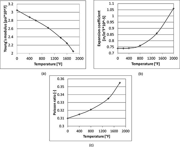 ) and Table (1).
 |
Fig. (1) Material properties vs. temperature for the considered superalloy: (a) Young’s modulus, (b) Expansion coefficient; (c) Poisson’s ratio. |
Fluid pressure was modeled as a mechanical load applied on both sides of the airfoils, together with a temperature scenario previously calculated by thermo-fluid-dynamic analyses. In addition, cyclic symmetry boundary conditions Fig. (2a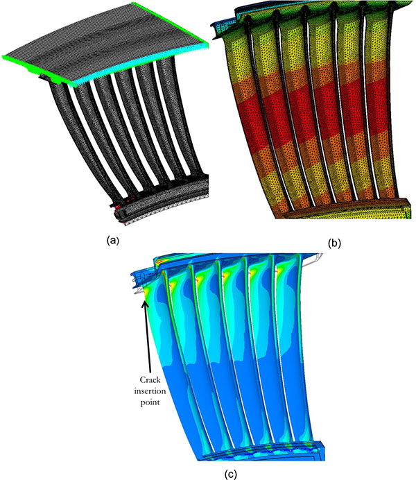 ) were enforced on a casing that couples with a statoric segment, in order to simulate the periodicity of the whole stage. Surface to surface contacts were applied on the interfaces between statoric hooks and casing. Thermal and mechanical loads applied on the global model are representative of the most severe conditions, reached at take-off, for an aircraft engine during its mission. As a matter of fact, at take-off there is the need for the maximum boost of engines and consequently vane temperatures Fig. (2b) get the highest magnitudes and the highest gradients, with consequent enhancement of thermal stresses.
 |
Fig. (2) (a) Cyclic symmetry FEM boundary conditions; (b) FEM thermal scenario; (c) FEM max principal stresses. |
Due to a combination of mechanical and thermal cyclic stresses, fatigue cracks can nucleate, most likely from those locations with highest stresses localized in-between airfoils and casing (Fig. 2c).
DBEM SUBMODELLING APPROACH
Introduction
A simplified thermo-mechanical fatigue load cycle was extracted from the mission profile Fig. (3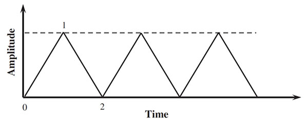 ), with its maximum value corresponding to the take-off phase and its minimum value to the engine shut off (zero load).
 |
Fig. (3) Engine mission profile. |
Mechanical, thermal and fatigue properties for the considered superalloy were evaluated at the average temperature of sub-model. In particular the calibration of the Paris’ law (Eq. 1), adopted to calculate crack growth rates, was performed at such average temperature.
 |
(1) |
The DBEM submodel cannot allow for the spatial variability of the material properties, caused by temperature gradients and, consequently, uniform material properties were used, as evaluated in correspondence of an average temperature. Nevertheless, for the analyzed problem the impact of such approximation on the final results (e.g. Stress Intensity Factors (SIFs) along the crack front) turns out to be negligible, due to the limited temperature variation in a very small DBEM submodel.
SIFs are calculated using the J-integral approach [25D.N. Dell’Erba, M.H. Aliabadi, and D.P. Rooke, "Dual boundary element method for three-dimensional thermoelastic crack problems", Int. J. Fract., vol. 94, no. 1, pp. 89-101, 1998.
[http://dx.doi.org/10.1023/A:1007572726097] -27R.H. Rigby, and M.H. Aliabadi, "Mixed-mode J-integral method for analysis of 3D fracture problems using DBEM", Eng. Anal. Bound. Elem., vol. 11, pp. 239-256, 1993.
[http://dx.doi.org/10.1016/0955-7997(93)90026-H] ] and the crack path assessment is based on the Minimum Strain Energy Density (MSED) criterion [28G.C. Sih, and B.C. Cha, "A fracture criterion for three-dimensional crack problems", J. Eng. Fract. Mech., vol. 6, pp. 699-732, 1974.
[http://dx.doi.org/10.1016/0013-7944(74)90068-X] ] (actually, the comparison between outcomes of different crack path criteria was not provided because the crack propagation evolves under nearly pure mode I).
DBEM Modelling Considering “LC” and “DC” Approaches
Two different methodologies were considered in order to calculate a SIF distribution along crack front:
-
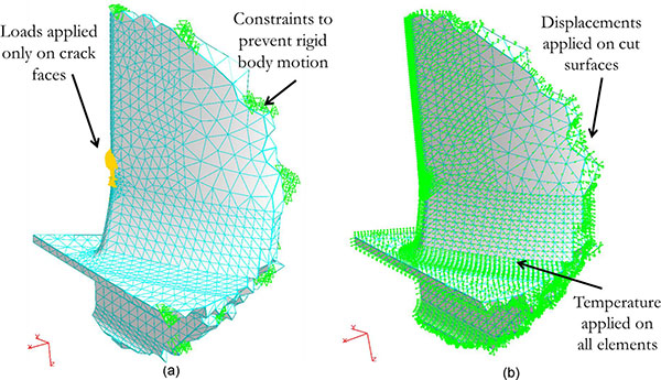
Crack surface loading problem (hereafter named “LC”): tractions, evaluated along the virtual surface traced by the advancing crack by means of a FEM analysis of the uncracked component, were applied on the crack faces in the DBEM submodel. In particular, the DBEM evolving crack geometry “filters”, at each step of crack propagation, the stresses to be extracted from the solution of the FE uncracked model; then such stresses are converted in tractions to be applied on the crack faces (Fig. 4a
 ).
).
- Displacement Control (DC) approach: displacement and temperature scenarios, calculated by an FEM analysis of the global uncracked component, were imported into DBEM environment and applied on cut surfaces; in addition, FE temperatures were applied on all the remaining DBEM elements Fig. (4b). Fluid pressure on airfoil was not modelled because causing negligible effects, but no difficulties would arise in adding such pressure too. Moreover, no volume forces are present in the submodel domain (it is part of a vane so with no centrifugal loads).
Both DC and LC methodologies eventually provide SIF distributions along the crack front but following two different approaches: the former solves a thermal-stress analysis; the latter solely need a pure stress analysis. LC approach thus avoids the need for a combined thermal-stress problem and can leverage on a coarser convergent mesh with consequent run time reduction. On the other hand, LC approach can provide a realistic stress scenario just in an infinitesimal area surrounding the crack tip, so cannot be adopted when an overall knowledge of stress distribution is needed.
 |
Fig. (4) Considered loading strategies for DBEM analyses: (a) LC and (b) DC. |
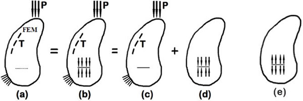 |
Fig. (5) Superposition principle applied to a thermal-stress crack problem. |
In particular, a superposition principle is implemented through the following steps (Fig 5 ):
):
- starting from an original uncracked model (a), a crack can be opened (b) and then closed again by the distribution of tractions calculated over the dashed line of the virtual crack in (a);
- the new configuration (b), perfectly equivalent to the previous one (a), can be solved using a superposition principle by splitting the boundary conditions as illustrated in (c) and (d): (c) represents the original problem that we need to solve whereas, the problem (d) that is identical to (e) but for the sign of crack tractions, represents an alternative equivalent problem that will be solved, gaining substantial improvements in terms of accuracy and computational burden. As a matter of fact, using boundary conditions coming from the considered thermal-stress uncracked problem, a pure stress crack problem (e) can be solved, in which crack faces are subjected to tractions equal in magnitude but opposite in sign to those calculated over the dashed line in (a).
In conclusion, using the superposition principle it is possible to state that SIFs for case (c) are equal to those calculated for case (e):
 |
(2) |
 |
(3) |
Using the LC approach, an uncracked FEM model is solved to accurately calculate the stress field in the surroundings the cracked zone, whereas, the fracture problem is entirely demanded to the DBEM analysis. All the loads applied to the real component (e.g. thermal, electro-magnetic, dead weight, bolt preloadings) are included in the FEM analysis, whereas, the SIFs evaluation and subsequently the whole crack-growth is worked out into the DBEM environment by means of a step-by-step pure stress analyses.
 |
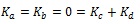
Fig. (6) DBEM submodel sizes: mesh before crack introduction and highlight of crack site. |
A further benefit of such LC approach is given by the possibility to simulate crack propagations with a considerably smaller model than needed by DC approach, as enabled by the self-equilibrated nature of the load applied with LC and its rapidly vanishing effects when getting far apart from the crack. Such reduction of the DBEM domain will strongly speed up the analyses.
DBEM Modelling Considering Different Submodel Sizes
A small portion of the whole FE model was extracted by a spherical cut and converted in a DBEM sub-model by a skinning procedure; then a crack was introduced and the crack propagation simulated.
In particular, two submodels Fig (6 ), centered in the same position (crack initiation point) but of different sizes, obtained by a R=1 and R=0.3 inch cutting sphere radius respectively, were imported in a DBEM environment and solved in order to assess the minimum submodel size needed to guarantee insensitivity of boundary conditions against crack growth.
It is worth to point out that using DC procedure without update of boundary conditions during crack growth, there is no allowance for stiffness variation of the volume surrounding the crack, so that a submodel sufficiently larger than crack sizes is needed. Such drawback can be circumvented by using LC approach, where the submodel minimum size can be much lower, with consequent reduction of computational effort. As a matter of fact, having solely applied a self-equilibrated load on the crack faces, it is sufficient to enclose in the sphere cut just a restricted volume portion surrounding the crack that is affected by non-null stresses, as shown in the following.
FEM-DBEM RESULTS
DBEM Results Considering LC and DC Approaches and Different Submodel Sizes
As previously mentioned, two submodels with different sizes were extracted by a sphere cutting and then solved. The aim was to assess the minimum required submodel size when using DC approach, “compatible” with boundary conditions that were not updated during crack growth.
In more details, submodel boundary conditions for both DC and LC approaches come from the FEM analysis of the uncracked global model but, for the DC approach this represents an element of approximation because the displacement boundary conditions applied on the cutting surfaces should, in principle, be updated at each step of crack advance, so as to allow for the submodel stiffness variation when solving the global model. On the contrary, in LC approach the self-equilibrated tractions applied on crack faces are correctly extracted from an uncracked body solution, as rigorously dictated by the superposition principle implementation and, during crack propagation, are updated step by step because new crack surface is continuously created and loaded. Consequently, for LC approach there is no need to guarantee a submodel much larger than crack extension, being sufficient to enclose that part of the volume surrounding the crack where stresses are non negligible; moreover it is worth to point out that the stress “fading distance” is very short when a self-equilibrated load is applied on the crack.
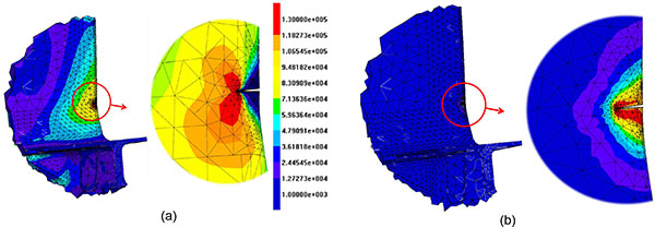 |
Fig. (7) (a) Von Mises stresses [psi] for the initial cracked DC and (b) LC models, with close-up of the cracked area (cutting sphere radius R= 1 inch). |
A crack was modeled and inserted in both LC and DC models; crack sizes are representative of the maximum tolerable defect as dictated by GE-AVIO regulations. Introducing such a crack into a DBEM submodel, with consequent automatic remeshing in the cracked area, two different stress scenarios came out from DC and LC approaches Fig. (7 ): the former produces a realistic stress scenario throughout the whole DBEM submodel whereas the latter provides a realistic stress scenario just in the surrounding of the infinitesimal crack tip area; hence, a comparison between the two methodologies can just concern SIFs along the crack front.
A convergence study Fig. (8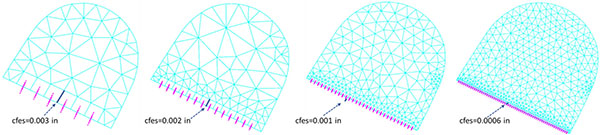 ) was provided for each of the two methodologies (DC and LC), varying the submodel size and the mesh on and nearby the crack, in order to benchmark the respective convergence rates and run time efficiencies.
 |
Fig. (8) Different meshes on the crack face, as used for the convergence study (the setting parameter “cfes” is the crack front element size” [24BEASY, BEASY V10r14 Documentation., C.M. BEASY Ltd, 2011.]). |
Analyzing the SIFs trend, it is possible to observe a high convergence rate for LC methodology, rapidly providing a convergent SIF distribution. As a matter of fact, from Fig. (9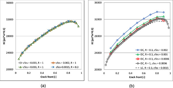 ) it is possible to see that the distribution of KI along the crack front is insensitive of mesh refining and consequently results corresponding to the mesh with crack front element size equal to 0.003 in are already convergent; moreover same results are obtained with different submodel sizes (R=1 in and R=0.3 in) proving that the smaller submodel size R=0.3 is sufficient to provide accurate results. On the contrary the DC approach need a stronger mesh refinement in order to reach convergence (cfes=0.0006 in); again the smaller submodel size is sufficient to provide accurate results as proven by the overlap of KI profiles for both submodel sizes (R=1 in and R=0.3 in).
 |
Fig. (9) KI values along crack front of the initial crack: LC (a) and DC (b) methodologies, considering different mesh (cfes=…) and submodel (R=…) sizes. |
Even if KII and KIII values are one order of magnitude lower than KI values, from Fig. (10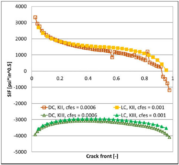 ) it is possible to appreciate the substantial coincidence of respective convergent results when using DC and LC approach, but it is worth to emphasize that the DC methodology can only reach convergence on KII and KIII values after a stronger mesh refinement.
 |
Fig. (10) Comparison between LC and DC convergent KII and KIII values for the larger submodel (R=1). |
The nearly perfect coincidence of the results provided by the two LC and DC methodologies in correspondence of the initial cracked configuration Figs. (9b-10) guarantees the correct implementation of the proposed LC alternative approach.
Afterwards, a crack propagation simulation has been performed with both LC and DC methodologies but convergent crack propagation results related to DC approach could not be calculated due to the excessive mesh refinement needed and consequent prohibitive run times.
Crack shape vs. cycles, calculated with LC and DC methodologies, are compared in Fig. (11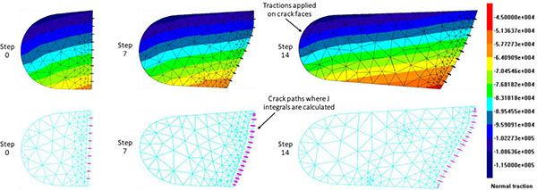 ): again a strong similarity of the DC vs. LC crack configurations can be noted, showing the equivalence for the two proposed methods. Crack propagation has been stopped when the maximum SIF effective (Eq. 4) [24BEASY, BEASY V10r14 Documentation., C.M. BEASY Ltd, 2011.], which in this case is nearly coincident with KI due to the reduced level of mode-mixity, reaches 96% of fracture toughness Kc Fig. (12
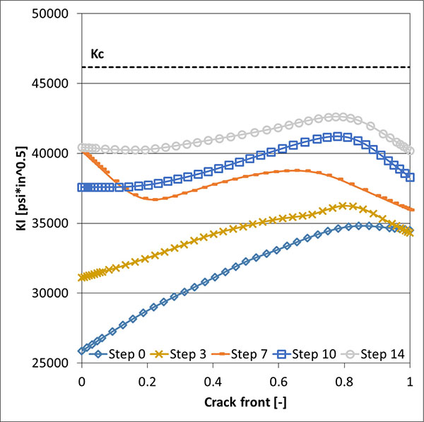 ). As previously said, it was difficult to obtain convergence along crack propagation with DC approach and that is why in (Fig. 12) only the LC results are displayed.
 |
Fig. (11) Crack shapes as provided by LC approach, with highlight of normal tractions (psi) introduced on crack faces (up), and DC approach (down). |
 |
Fig. (12) KI values along the crack front during propagation with LC approach (R=1). |
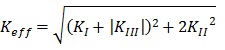 |
(4) |
LC SIFs for both smaller and larger submodels are nearly overlapped along the whole propagation Fig. (13a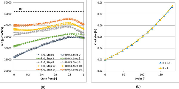 ) and consequently the same holds true for the crack size vs. cycles Fig. (13b): this shows that the smaller submodel (R=0.3) can be used for the whole crack propagation analysis when using the LC approach. On the contrary, SIFs from DC approach are overlapped for smaller and larger submodels just for the initial crack propagation steps Fig. (14a
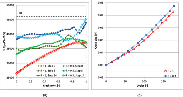 ), when cutting surfaces are still sufficiently far from advancing crack, but with a progressive divarication between the curves of crack size vs. cycles as the crack grows Fig. (14b). This show that the smaller submodel is not suitable to provide accurate results along the whole crack propagation when using DC approach. In conclusion, the performed analyses clearly shows that the LC approach allows to consider a smaller submodel than DC approach, without affecting the accuracy, with a consequent benefit in terms of run times for the problem solution.
 |
Fig. (13) Comparison of Keff along crack front (a) and equivalent crack size vs. cycles (b) for smaller and larger submodels with LC approach. |
 |
Fig. (14) Comparison of Keff along crack front and crack size vs. cycles for smaller and larger submodels with DC approach. |
From Fig (13), it is interesting to observe how the Keff values becomes substantially constant along the crack front when the crack propagation proceeds, as a consequence of the crack front profile changes dictated by implementation of Eq. 1, with ΔK= ΔKeff. Such behavior is not replicated in Fig. (14), where a certain degree of fluctuations on Keff along the crack fronts is obtained, but this is expected considering the lack of a strict convergence when simulating crack propagation with DC approach.
Runtime Comparison
The DBEM analyses, performed considering different submodel sizes (R=0.3 vs. R=1 inch) and different approaches (LC vs. DC), are now compared in terms of runtimes. With the constraint of choosing for each kind of analysis a mesh adequate to provide convergent results, runtimes related to the solution of the initial edge crack scenario (step 0) are compared (Table 2). In order to obtain the same accuracy on SIFs assessment, the adopted meshes are:
- crack front element size equal to 0.0006 inches for DC model;
- crack front element size equal to 0.002 inches for LC model.
CONCLUSION
A coupled FEM-DBEM procedure based on loaded crack faces (LC), was implemented for a crack propagation simulation on a GE-Avio aeroengine turbine vane. A benchmark of such alternative approach (LC) against a “standard” FEM-DBEM procedure (DC) was realized in order to highlight runtimes and accuracy improvements obtained with LC. As a matter of fact, LC approach allows to predict SIFs, crack growth rates as well as paths with higher accuracy and lower runtimes than DC approach, mainly because it involves pure stress analyses instead of thermal-stress calculations needed in DC procedure and because a less refined mesh is needed to get convergence results.
LC approach accuracy is enhanced because the boundary conditions on the advancing crack are in principle “correct” and continuously updated during the propagation, whereas DC approach is based on boundary conditions calculated from a global model with no allowance for crack presence and, what is more, with no update during crack growth. Consequently, LC guarantees a lower sensitivity of results against distance between cutting surfaces and crack as previously shown considering different submodel sizes.
CONFLICT OF INTEREST
The authors confirm that this article content has no conflict of interest.
ACKNOWLEDGEMENTS
Declared none.
REFERENCES
| [1] | R. Citarella, G. Cricrì, M. Lepore, and M. Perrella, "Thermo-mechanical crack propagation in aircraft engine vane by coupled FEM-DBEM approach", Adv. Eng. Software, vol. 67, pp. 57-69, 2014. [http://dx.doi.org/10.1016/j.advengsoft.2013.07.006] |
| [2] | C. Calì, G. Cricrì, and M. Perrella, "An advanced creep model allowing for hardening and damage effects", Strain, vol. 46, no. 4, pp. 347-357, 2010. [http://dx.doi.org/10.1111/j.1475-1305.2009.00682.x] |
| [3] | R. Citarella, and G. Cricrì, "Comparison of DBEM and FEM crack path predictions in a notched shaft under torsion", Eng. Fract. Mech., vol. 77, pp. 1730-1749, 2010. [http://dx.doi.org/10.1016/j.engfracmech.2010.03.012] |
| [4] | R. Citarella, and F.G. Buchholz, "Comparison of crack growth simulation by DBEM and FEM for SEN-specimens undergoing torsion or bending loading", Eng. Fract. Mech., vol. 75, pp. 489-509, 2008. [http://dx.doi.org/10.1016/j.engfracmech.2007.03.039] |
| [5] | A.R. Maligno, R. Citarella, V.V. Silberschmidt, and C. Soutis, "Assessment of structural integrity of subsea wellhead system: Analytical and numerical study", Fract. Struct. Integrity, vol. 31, pp. 97-119, 2015. [http://dx.doi.org/10.3221/IGF-ESIS.31.08] |
| [6] | R. Citarella, M. Lepore, A. Maligno, and V. Shlyannikov, "FEM simulation of a crack propagation in a round bar under combined tension and torsion fatigue loading", Fract. Struct. Integrity, vol. 31, pp. 138-147, 2015. [http://dx.doi.org/10.3221/IGF-ESIS.31.11] |
| [7] | R. Citarella, M. Lepore, V. Shlyannikov, and R. Yarullin, "Fatigue surface crack growth in cylindrical specimen under combined loading", Eng. Fract. Mech., vol. 131, pp. 439-453, 2014. [http://dx.doi.org/10.1016/j.engfracmech.2014.08.017] |
| [8] | R. Citarella, and M. Perrella, "Multiple surface crack propagation: numerical simulations and experimental tests", Fatigue Fract. Eng. Mater. Struct., vol. 28, pp. 135-148, 2005. [http://dx.doi.org/10.1111/j.1460-2695.2004.00842.x] |
| [9] | C. Calì, R. Citarella, and M. Perrella, "Three-dimensional crack growth: numerical evaluations and experimental tests", Eur. Struc. Integrity Soc., vol. 31, no. 3, pp. 341-360, 2003. [http://dx.doi.org/10.1016/S1566-1369(03)80019-5] |
| [10] | R. Citarella, G. Cricrì, M. Lepore, and M. Perrella, "DBEM and FEM analysis of an extrusion press fatigue failure", Adv. Struc. Mater., vol. 3, pp. 181-191, 2010. [http://dx.doi.org/10.1007/978-3-642-12667-3_12] |
| [11] | R. Citarella, and G. Cricrì, "Three-Dimensional BEM and FEM Submodelling in a Cracked FML Full Scale Aeronautic Panel", Appl. Compos. Mater., vol. 21, no. 3, pp. 557-577, 2014. [http://dx.doi.org/10.1007/s10443-014-9384-5] |
| [12] | R. Citarella, M. Lepore, J. Fellinger, V. Bykov, and F. Schauer, "Coupled FEM-DBEM method to assess crack growth in magnet system of Wendelstein 7-X", Fract. Struct. Integrity, vol. 26, pp. 92-103, 2013. [http://dx.doi.org/10.3221/IGF-ESIS.26.10.92] |
| [13] | R. Citarella, M. Lepore, M. Perrella, and J. Fellinger, "Coupled FEM–DBEM approach on multiple crack growth in cryogenic magnet system of nuclear fusion experiment ‘Wendelstein 7-X", Fatigue Fract. Eng. Mater. Struc., vol. 39, no. 12, pp. 1-14, 2016. [http://dx.doi.org/10.1111/ffe.12466] |
| [14] | R. Citarella, G. Cricrì, M. Lepore, and M. Perrella, "Assessment of crack growth from a cold worked hole by coupled FEM-DBEM approach", Key Eng. Mater., vol. 577-578, pp. 669-672, 2014. Trans Tech Publications: Switzerland. |
| [15] | P. Carlone, R. Citarella, M. Lepore, and G.S. Palazzo, "A FEM-DBEM investigation of the influence of process parameters on crack growth in aluminium friction stir welded butt joints", Int. J. Mater. Form., vol. 8, no. 4, pp. 591-599, 2015. [http://dx.doi.org/10.1007/s12289-014-1186-7] |
| [16] | R. Citarella, P. Carlone, M. Lepore, and G.S. Palazzo, "Numerical-experimental crack growth analysis in AA2024-T3 FSWed butt joints", Adv. Eng. Softw., vol. 80, pp. 47-57, 2015. [http://dx.doi.org/10.1016/j.advengsoft.2014.09.018] |
| [17] | R. Citarella, P. Carlone, R. Sepe, and M. Lepore, "DBEM crack propagation in friction stir welded aluminum joints", Adv. Eng. Softw., vol. 101, pp. 50-59, 2016. [http://dx.doi.org/10.1016/j.advengsoft.2015.12.002] |
| [18] | R. Citarella, P. Carlone, M. Lepore, and R. Sepe, "Hybrid technique to assess the fatigue performance of multiple cracked FSW joints", Eng. Fract. Mech., vol. 162, pp. 38-50, 2016. [http://dx.doi.org/10.1016/j.engfracmech.2016.05.005] |
| [19] | R. Citarella, and G. Cricrì, "A two-parameter model for crack growth simulation by combined FEM-DBEM approach", Adv. Eng. Softw., vol. 40, no. 5, pp. 363-377, 2009. [http://dx.doi.org/10.1016/j.advengsoft.2008.05.001] |
| [20] | R. Citarella, V. Giannella, E. Vivo, and M. Mazzeo, "FEM-DBEM approach for crack propagation in a low pressure aeroengine turbine vane segment", Theor. Appl. Fract. Mech., vol. 86, pp. 143-152, 2016. [http://dx.doi.org/10.1016/j.tafmec.2016.05.004] |
| [21] | W.K. Wilson, "The use of the J-integral in thermal stress crack problems", Int. J. Fract., vol. 15, no. 4, pp. 377-387, 1979. |
| [22] | V. Mallardo, M.H. Aliabadi, A. Brancati, and V. Marant, "An accelerated BEM for simulation of noise control in the aircraft cabin", Aerosp. Sci. Technol., vol. 23, no. 1, pp. 418-428, 2012. [http://dx.doi.org/10.1016/j.ast.2011.10.001] |
| [23] | ANSYS, ANSYS Release 11 Documentation., ANSYS Inc.: United States of America, 2007. |
| [24] | BEASY, BEASY V10r14 Documentation., C.M. BEASY Ltd, 2011. |
| [25] | D.N. Dell’Erba, M.H. Aliabadi, and D.P. Rooke, "Dual boundary element method for three-dimensional thermoelastic crack problems", Int. J. Fract., vol. 94, no. 1, pp. 89-101, 1998. [http://dx.doi.org/10.1023/A:1007572726097] |
| [26] | D.N. Dell’Erba, and M.H. Aliabadi, "DBEM analysis of fracture problems in three dimensional thermoelasticity using J-integral", Int. J. Solids Struct., vol. 38, no. 26–27, pp. 4609-4630, 2001. [http://dx.doi.org/10.1016/S0020-7683(00)00305-X] |
| [27] | R.H. Rigby, and M.H. Aliabadi, "Mixed-mode J-integral method for analysis of 3D fracture problems using DBEM", Eng. Anal. Bound. Elem., vol. 11, pp. 239-256, 1993. [http://dx.doi.org/10.1016/0955-7997(93)90026-H] |
| [28] | G.C. Sih, and B.C. Cha, "A fracture criterion for three-dimensional crack problems", J. Eng. Fract. Mech., vol. 6, pp. 699-732, 1974. [http://dx.doi.org/10.1016/0013-7944(74)90068-X] |