- Home
- About Journals
-
Information for Authors/ReviewersEditorial Policies
Publication Fee
Publication Cycle - Process Flowchart
Online Manuscript Submission and Tracking System
Publishing Ethics and Rectitude
Authorship
Author Benefits
Reviewer Guidelines
Guest Editor Guidelines
Peer Review Workflow
Quick Track Option
Copyediting Services
Bentham Open Membership
Bentham Open Advisory Board
Archiving Policies
Fabricating and Stating False Information
Post Publication Discussions and Corrections
Editorial Management
Advertise With Us
Funding Agencies
Rate List
Kudos
General FAQs
Special Fee Waivers and Discounts
- Contact
- Help
- About Us
- Search


The Open Mechanical Engineering Journal
(Discontinued)
ISSN: 1874-155X ― Volume 14, 2020
Revised Lewis Bending Stress Capacity Model
Edward. E. Osakue1, *, Lucky Anetor2
Abstract
Background:
During operation, cylindrical gearset experiences tangential, radial, and axial (helical gears only) force components that induce bending, compressive, and shear stresses at the root area of the gear tooth. Accurate estimation of the effective bending stress at the gear root is a challenge. Lewis was the first person who attempted estimating the root bending stress of spur gears with some reasonable accuracy. Various gear standards and codes in use today are modifications and improvements of the Lewis model.
Objective:
This research aims at revising the Lewis model by making adjustments for dynamic loads, shear stresses, axial bending stress for helical gears, and stress concentration factor that is independent on the moment arm of tangential or axial force component.
Methods:
An analytical approach is used in formulating a modified formula for the root bending stress in cylindrical gears starting with the original Lewis model. Intermediate expressions are developed in the process and works from many previous authors are reviewed and summarized. The new model developed is used to estimate the root bending stress in four example gearsets of 0o to 41.41o helix angle and the results are compared with those of AGMA (American Gear Manufacturers Association) formula.
Results:
Analysis from the examples shows that neglecting the radial compressive stress over-estimated the root bending stress by 5.27% on average. When shear stresses are ignored, the root bending stress is under-estimated by 7.49% on average. It is important, therefore, to account for both compressive and shear stresses in cylindrical gear root bending stress. When the root bending stress estimates from the revised Lewis model were compared with AGMA results, deviations in the range of -4.86% to 26.61% were observed. The stress estimates from the revised Lewis formulae were mostly higher than those of AGMA.
Conclusion:
The new root bending stress model uses stress concentration factors (normal and shear) that are independent of the point of load application on the gear tooth. This decoupling of stress concentration factor from the load moment arm distinguishes the new model from AGMA formula and brings bending stress analysis in gear design in line with classical bending stress analysis of straight and curved beams. The model can be used for both normal contact ratio and high contact ratio cylindrical gears.
Article Information

Identifiers and Pagination:
Year: 2020Volume: 14
First Page: 1
Last Page: 14
Publisher Id: TOMEJ-14-1
DOI: 10.2174/1874155X02014010001
Article History:
Received Date: 16/01/2020Revision Received Date: 26/05/2020
Acceptance Date: 26/05/2020
Electronic publication date: 31/07/2020
Collection year: 2020
open-access license: This is an open access article distributed under the terms of the Creative Commons Attribution 4.0 International Public License (CC-BY 4.0), a copy of which is available at: https://creativecommons.org/licenses/by/4.0/legalcode. This license permits unrestricted use, distribution, and reproduction in any medium, provided the original author and source are credited.
* Address correspondence to this author at the Department of Industrial Technology, Texas Southern University, Houston, Texas, USA; Tel: 832-316-3279; E-mail: edward.osakue@tsu.edu
| Open Peer Review Details | |||
|---|---|---|---|
| Manuscript submitted on 16-01-2020 |
Original Manuscript | Revised Lewis Bending Stress Capacity Model | |
1. INTRODUCTION
A gear is a toothed disk used to transmit power and motion when mounted on a rotating shaft. Cylindrical gears have teeth-
cut on a cylinder and are typically divided into spur and helical gear types. Spur gears have teeth projecting radially and parallel to the axis of the shaft and they have been used since ancient times [1Spur Gear Terms and Concepts.http://www.gearseds.com/files/6.3.1
_Gear_Terms_Lesson_rev3.pdf]. A helical gear has teeth wrapped like a screw on its pitch cylinder though the pitch surface is cylindrical as in spur gears [2R.S. Khurmi, and J.K. Gupta, A Textbook of Machine Design., Eurasia Publishing House: New Delhi, p. 1066.]. The helix may be right-handed or left-handed and its inclination to the axial direction is called the helix angle. A spur gear may be treated as a helical gear with a zero-helix angle [3J.A. Collins, H. Busby, and G.H. Staab, Mechanical Design of Machine Elements and Machines: A Failure Prevention Perspective., 2nd edJohn Wiley and Sons: New York, .
]. The helix allows more gradual engagement of meshing teeth, which results in a smoother transfer of load from the driving teeth to the driven teeth. Therefore, helical gears are increasingly being used because of their relatively smooth and quiet operation, large load carrying capacity, and higher operating speed [4J.R. Partridge, High Speed Gears-Design and Applications.http://turbolab.tamu.edu/proc/turboproc/T6/T6pg133-142.pdf, 5A. Y. Gidado, I. Muhammad, and A. A. Umar, "Design, modeling and analysis of helical gear according to bending strength using AGMA and ANSYS", Int’l Journal of Engineering Trends and
Technology, vol. 8, no. 9, .].
The resistance of gear teeth to failure in bending is called beam strength and gear failure in bending fatigue is a common problem [6R.L. Mott, Machine Elements in Mechanical Design, 4th edSI, Pearson Prentice Hall, New York, . Chap.-8S.R. Schmid, B.J. Hamrock, and B.O. Jacobson, Fundamentals of Machine Elements., 3rd edCRC Press: New York, .
[http://dx.doi.org/10.1201/b17120] ]. In 1892, Lewis modeled a gear tooth as a short cantilever beam on a rigid base with the transmitted load applied near the tip of the gear tooth [9V.S.N.K. Bommisetty, Finite element analysis of spur gear set, masters, Thesis, Mechanical Engineering Department, Cleveland State University, ., 10A. Kawalec, J. Wiktor, and D. Ceglarek, "Comparative analysis of tooth-root strength using iso and agma standards in spur and helical gears with fem-bases verification", J. Mech. Des., vol. 128, pp. 1141-1158.
[http://dx.doi.org/10.1115/1.2214735] ]. The maximum tensile stress occurs at the root radius on the loaded or active side of the gear tooth. Due to the repeated loading of a gear tooth, this region becomes the preferential site for the initiation of a fatigue crack. Fatigue failure is due to crack formation and propagation induced by repeated loading. A crack normally initiates at a discontinuity where there is a cyclic maximum stress [9V.S.N.K. Bommisetty, Finite element analysis of spur gear set, masters, Thesis, Mechanical Engineering Department, Cleveland State University, ., 10A. Kawalec, J. Wiktor, and D. Ceglarek, "Comparative analysis of tooth-root strength using iso and agma standards in spur and helical gears with fem-bases verification", J. Mech. Des., vol. 128, pp. 1141-1158.
[http://dx.doi.org/10.1115/1.2214735] ]. Cracks grow along planes normal to the maximum tensile stress [9V.S.N.K. Bommisetty, Finite element analysis of spur gear set, masters, Thesis, Mechanical Engineering Department, Cleveland State University, .] and when the growth becomes unstable, brittle fracture rapidly follows. Thru-hardened gears most often fail in bending fatigue due to a crack initiated at the surface in the root area. Because the surface hardness of case-hardened gears is higher than the core value, the bending fatigue strength of the gear root surface can be higher than that of the core. Case-hardened gears generally fail in fatigue at the boundary of case-core hardness, except when there is a sharp stress raiser at the surface [11Z.K. Dobrovolsky, S. Mak, A. Radchik, and L. Erlikh, Machine Elements., Foreign Language Pub. House: Moscow, pp. 33-34, 279-289.].
Case-hardening processes, such as induction hardening, flame hardening, carburizing, nitriding, and some other processes like shot-peening, hammering, and cold rolling, can increase the fatigue resistance of gears because they generate surface compressive residual stresses [12R.G. Budynas, and J.K. Nissbett, Shigley’s Mechanical Engineering Design, 9th edMcGraw Hill Education: Delhi, pp. 230-232; 293.-16B. LeMaster, J. Boggs, C. Hubbard Bunn, and T. Watkins, "Grinding Induced Changes in Residual Stresses of Carburized Gears", Gear Technology, pp. 42-49.]. The surface stresses tend to weaken the effects of stress raisers reducing fatigue damage. Finishing processes, such as grinding or skiving, tend to develop tensile residual stresses, thereby reducing the benefits of compressive residual stress in case-hardening processes, but some compressive surface residual stresses usually persist.
2. MOTIVATIONS AND OBJECTIVE OF THE STUDY
The tangential load in spur gears induces both bending and direct shear stresses on the gear tooth, while the radial load produces only compressive stress. In helical gears, an axial load exists and it introduces both bending and shear stresses, in addition to those experienced by spur gears. The bending stress capacity models of American Gear Manufacturers Association (AGMA), International Standardization Organization (ISO), and Japanese Industrial Standards (JIS) account for the bending stress from the tangential force, compressive stress from the radial load and the effect of stress concentration, but not explicitly, for the shear stresses which are considered negligible. Accounting for shear stresses will improve the estimation of gear root bending stress.
The AGMA model is based on the load point being at the worst position, which corresponds to the highest point of single tooth contact (HPSTC) in a gear mesh for normal contact ratio gears. In normal contact ratio gear meshes, the contact ratio is less than 2. Gear meshes with a contact ratio of at least 2 are described as high contact ratio gears and multiple gear pairs are always in contact during operation. In normal contact ratio gears, one pair of gear teeth carries the transmitted load at HPSTC in the AGMA model, but near the tip of the gear, two pairs carry the transmitted load, indicating that load sharing occurs. The main issue in high contact ratio gears is the identification of the point of contact that results in the maximum bending stress for each tooth and whether that point occurs simultaneously for all the teeth in the mesh [17D.W. Dudley, Handbook of Practical Gear Design, CRC Press: Baca Raton, pp. 2.10-2.11.]. Hence the concept of “HPSTC” seems inapplicable when multiple pairs of teeth are in contact in a mesh. AGMA, therefore, has two bending stress capacity models for cylindrical gears, based on contact ratio. Also, the computation of the J-value in the AGMA formula is evaluated for HPSTC, which is complicated, especially for addendum corrected gearsets.
The AGMA bending stress concentration factor model is based on the work of Dolan and Broghamer, who experimented on photoelastic plastic gear materials. The stress concentration factor is related to the bending moment arm, which makes it to be dependent on the point of load application on the gear tooth. In classical stress concentration analysis of straight and curved beams, the location of the bending load on the beam does not affect the stress concentration factor. In these cases, the stress concentration factor is dependent on the local geometry and the notch sensitivity of the component material. This appears to be an obvious weakness of the AGMA bending capacity models. Another issue is that tests on metal gears suggest that the stress concentration factor obtained is not the same as that for photoelastic plastic gears [17D.W. Dudley, Handbook of Practical Gear Design, CRC Press: Baca Raton, pp. 2.10-2.11.]. The actual stress concentration value depends on the presence of deep tool marks and scratches (surface roughness), surface hardness, surface residual compressive stress, and load cycles [17D.W. Dudley, Handbook of Practical Gear Design, CRC Press: Baca Raton, pp. 2.10-2.11., 18J.E. Shigley, and C.R. Mischke, Standard Handbook of Machine Design, McGraw-Hill, New York, . Chap 13.]. Stress concentration arises from changes in the cross-sectional dimensions of components that are under stress [19Stress Concentration Factors and Notch Sensitivity.https://moodlearn.ariel.ac.il/pluginfile.php/456050/mod_resource/content/0/Stress-consentration.pdf].
As mentioned earlier, contact of two gear pairs occurs even in normal contact ratio meshes near the gear tips. Hence, in general, multiple pairs of gear teeth contacts exist in all gear meshes, but it is perhaps impossible to locate HPSTC for high contact ratio gear meshes. Because load sharing occurs near the gear tip in all gear meshes and the Lewis model assumes a load point near the gear tip, the model appears to hold promise in estimating gear bending stress for both normal and high contact ratio gear meshes. The Lewis model is also attractive due to the computational simplicity of the bending stress form factor. The objective of this study is to modify Lewis bending stress model such that it accommodates stress concentration factor that is independent of load application point and accounts for shear stresses in the root bending stress of cylindrical gears.
3. FORCES IN CYLINDRICAL GEARS
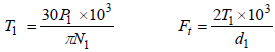
The power transmitted by a gearset generates torque and force loads that must be safely carried by the gears. Fig. (1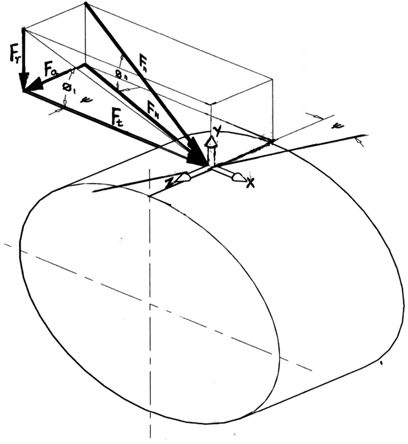 ) shows the forces generated during power transmission in helical gears. The torque and tangential force on the pinion tooth are:
 |
(1) |
 |
Fig. (1) Forces in helical gear. |
Equation (1) has two entries and should be interpreted as Eq. (1a) and Eq. (1b) from left to right. The same rule should be applied to other equations of similar nature. The subscript 1 in Eq. (1) applies to the pinion in a gearset. Similar equations can be deduced for the gear by using Eq.2 as a subscript.
The radial and axial forces in Fig. (1) are given in Eq. (2).
 |
(2) |
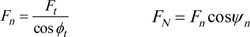
The normal forces in the gear mesh Fig. (1) are given by Eq. (3).
 |
(3) |
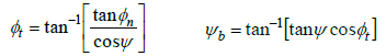
The influence of the helix angle in gear performance can be summarized by two parameters: the transverse pressure angle, and the base helix angle ѱb. The relationships of these parameters with the helix angle are given in Eq. (4).
 |
(4) |
At low helix angles, ѱ ≤ 20o [20E. E. Osakue, and L. Anetor, "Helical Gear Contact Fatigue Design by Spur Gear Equivalency", Int’l Journal of Research in Engineering and Technology, vol. 06, no. 02, .], the base helix angle is approximately equal to the helix angle. At high values of helix angle, a significant difference arises between the base helix angle and the helix angle.
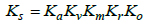
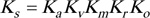
4. SERVICE LOAD FACTOR (Ks)
Experience shows that the forces acting on equipment in service are generally higher than the rated or nominal values in gear drives. Practically, the design or service load is often estimated by multiplying the rated load with a service load factor, which is used to account for load increases during normal operations of gearsets. It is a load magnification factor and in gear design, it may be evaluated by a multiplicative model as was done in a previous study [21E. Edward, "Osakue, Simplified Spur Gear Design", Proceedings of International Mechanical Engineering Congress and Exposition 2016 IMECE.]:
 |
(5) |
Readers are referred to Osakue [21E. Edward, "Osakue, Simplified Spur Gear Design", Proceedings of International Mechanical Engineering Congress and Exposition 2016 IMECE.], AGMA documents [22AGMA 2001-D04, Fundamental Rating Factors and
Calculation Methods for Involute Spur and Helical Gear Teeth:.http://wp.kntu.ac.ir/asgari/AGMA%202001-D04.pdf], Osakue and Anetor [23E. E. Osakue, and L Anetor, "Design of straight bevel gear for pitting resistance", FME Transactions, vol. 2, pp. 194-204.
[http://dx.doi.org/10.5937/fmet1802194O] ] for the selection of Ka and evaluation of KvKm and Kr. However, a brief summary of the parameters is given in Appendix B.
5. LEWIS BENDING CAPACITY MODEL
Gear failure in bending fatigue is one of the common modes of failure. The bending capacity of gear teeth was first calculated to a reasonable degree of accuracy by Wilfred Lewis in 1892 [9V.S.N.K. Bommisetty, Finite element analysis of spur gear set, masters, Thesis, Mechanical Engineering Department, Cleveland State University, .]. He considered a gear tooth as a cantilever beam on a rigid base with a maximum parabola inscribed inside the tooth shape. A parabolic shaped cross-sectional beam develops constant bending stress at the surface. For a gear loaded in bending, the maximum tensile stress occurs at the root radius on the loaded or active side of the gear tooth.
The assumptions made or implied in the derivation of the Lewis formula are [24K. Gopinath, and M.M. Mayuram, Machine Design II, Module 2 – GEARS, Lecture 7 - SPUR GEAR DESIGN.https://nptel.ac.in/courses/112106137/pdf/2_7.pdf, 25MECH 344:, Machine Element Design, Lecture 11.https://users.encs.concordia.ca/~nrskumar/Index_files/Mech344/Lectures/Lecture_11.pdf]:
1. The applied load is assumed to be static. In practice, it is dynamic and depends on several factors, therefore this assumption is not conservative. The internal dynamic overload factor component in the service load factor in Eq. (5) was introduced in gear design to remedy this problem.
2. The tangential or transmitted load is applied to the tip of a single tooth. This assumption is conservative because when gears mesh at the tip, more than one pair is usually in engagement. This means load sharing is ignored.
3. The transmitted load is distributed uniformly across the full face width. This is a non-conservative assumption and can be instrumental in gear failures involving wide teeth and misaligned or deflecting shafts. The mesh or mounting overload factor component of the service load factor in Eq. (5) is used to account for gear mesh misalignment, which leads to non-uniform load distribution over the gear face width.
4. The radial force component is negligible. This is a conservative assumption because it produces a compressive stress that subtracts from the tensile stress at the point of maximum stress.
5. Forces due to tooth sliding friction are negligible. This is reasonable since the sliding friction coefficient in properly lubricated gearsets is small. However, considering mesh friction improves the estimation of the bending stress at the gear root.
6. Shear stress from the transmitted load is ignored because it is considered negligible. This is a non-conservative assumption, though it seems reasonable. But considering them makes the bending stress estimate more realistic.
7. Stress concentration in the tooth fillet is negligible. Stress concentration effects were unknown in the time of Lewis but are now known to be important [19Stress Concentration Factors and Notch Sensitivity.https://moodlearn.ariel.ac.il/pluginfile.php/456050/mod_resource/content/0/Stress-consentration.pdf]. Therefore, stress concentration can no longer be ignored.
The Lewis formula may be expressed as:
 |
(6) |
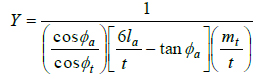
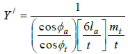
Eq. (6) is evaluated separately for the pinion and gear in gear design. The pinion is usually more vulnerable to bending stress failure, being of a smaller root tooth thickness. Eq. (7a) gives the expression for the modified Lewis bending stress form factor when the radial compressive stress is considered [26M. Petrov, D. Chernilevsky, and Y. Berezovsky, Machine Design., MIR: Moscow, pp. 137-139., 27Design for Strength, Lewis Bending Equation.https://images.search.yahoo.com/yhs/search]. Thus if the radial compressive force is neglected as assumed by Lewis, the Eq. (7b) is obtained.
 |
(7a) |
 |
(7b) |
It is clear that Eq. (7a) will always give higher values compared to Eq. (7b) because of the compressive stress considered in Eq. (7a) resulting in lower bending stresses. This explains why the value of Y for modern gear standards that account for the compressive radial force is slightly higher than Y/. Note that Y or Y/ values for the pinion and gear can be estimated from a single curve. This makes its use relatively easier than the AGMA-J values, which are evaluated at HPSTC and leads to the use of two separate curves, one for the pinion and the other for the gear. The AGMA-J value incorporates a stress concentration factor.
6. MODIFICATIONS OF LEWIS FORMULA
In general, when multiple teeth pairs are in contact in a mesh, then load shearing should be accounted for as in Eq. (8):
 |
(8) |
By incorporating the load sharing parameter  in Eq. (8), the bending stress in both normal and high contact ratio gears can be estimated using a single expression.
6.1. Tangential and Axial Bending Stresses
For helical gears, Eq. (8a) neglects the bending stress from the axial force and also the shear stresses from the transverse and axial forces. To account for these stresses, a fictitious spur gear is considered that has an axial load component in addition to a tangential load component, as depicted in Fig. (2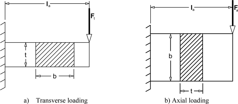 ). The gear tooth is modeled as a cantilever beam loaded in two planes in the Fig. (2a) is on the y-x or transverse plane of Fig. 1, while Fig. (2a) is on the y-z or axial plane of Fig. (1) The influence of the helix angle in actual helical gears will be considered later.
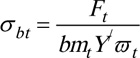
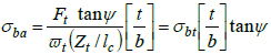
From Fig. (1a), the bending stress from the transverse load is:
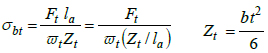 |
(9) |
From Fig. (1b), the bending stress from the axial load is:
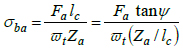 |
(10a) |
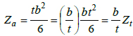 |
(10b) |
Substituting Eq. (9) in Eq. (10), we have:
 |
(11) |
 |
Fig. (2) Cantilever models of gear tooth in bending. |
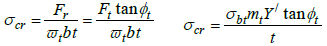
6.2. Direct Compressive Stress
The radial force induces a compressive stress, which is given in Eq. (12a). Eq. (12b) is obtained by combining Eq. (8) and Eq. (12a).
 |
(12) |
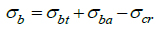
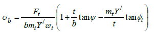
6.3. Combined Bending and Compressive Stresses
Considering the left diagram of Fig. 3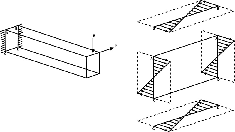 , where a beam of a rectangular cross-section is loaded in two planes. The two perpendicular forces produce bending moments about two axes: the vertical force about the horizontal axis and the horizontal force about the vertical axis at the centroid of the beam.
The distribution of the bending stresses from the forces at the cross-section is shown to the right of the loaded beam. At point A, the two bending stresses have positive values and they add up to give the maximum tensile stress. At point D, the two bending stresses have negative values and they added to give the maximum compressive stress. At point B or C, one bending stress is positive while the other is negative, therefore, the resultant stress in magnitude will be less than that for A or D. Since tensile stresses are responsible for fatigue failure, point A is the critical point in this figure. Applied to a gear tooth, one of the corner points at the root will experience additive tensile stresses.
By applying the above analysis to the gear tooth of Fig.(2); the maximum resultant bending tensile stress at one of the corners is given by Eq. (13a). Eq. (13b) is obtained by substituting Eq. (8), Eq. (11), and Eq. (12b) into Eq. (13a).
Eq. (13b) gives the estimate of the bending root stress from the bending influence of the tangential and axial forces in combination with the compressive radial force. But the shear stresses from both the tangential and axial forces are not accounted for. This is done in the next section.
 |
(13a) |
 |
(13b) |
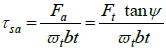
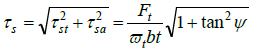
6.4. Direct Shear Stresses
The transverse and axial forces also induce direct shear stresses on the equivalent spur gear. The direct shear stress from the transverse load is:
 |
(14) |
The direct shear stress from the axial load is:
 |
(15) |
The tangential and axial shear stresses act on perpendicular planes, so the resultant shear stress is given in Eq. (16a). Eq. (16b) is obtained by substituting Eq. (8) into Eq. (16a).
 |
(16a) |
 |
(16b) |
 |
Fig. (3) Bending stress distribution in rectangular section. |
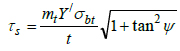
6.5. Equivalent Root Tensile Stress
The equivalent tensile stress at the gear root may be based on the distortion energy theory or maximum shear stress theory depending on whether the material is ductile or brittle [12R.G. Budynas, and J.K. Nissbett, Shigley’s Mechanical Engineering Design, 9th edMcGraw Hill Education: Delhi, pp. 230-232; 293., 28G.M. Maitra, Fundamentals of Toothed Gearing: Handbook of Gear Design., 2nd edMcGraw Hill: New Delhi, pp. 2.82-2.83.]. Most gears are made from ductile materials, so the equivalent tensile stress at the tooth root may be estimated by applying the distortion energy theory. For a plane stress situation, the equivalent tensile stress based on the distortion energy theory is:
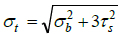 |
(17) |
7. REVISED LEWIS FORMULA
The dedendum circle is generally connected with the involute profile of a gear tooth with a fillet. This introduces a geometric discontinuity at the gear root resulting in stress concentration. The locations of size changes or discontinuity are sites of stress concentration where the maximum stress values are considerably higher than the nominal or average values. The ratio of the maximum stress to the nominal stress is generally called the stress concentration factor. Stress concentration was not known in the days of Lewis; but it is very important today because experimental and simulated results indicate that it can significantly increase local stresses [19Stress Concentration Factors and Notch Sensitivity.https://moodlearn.ariel.ac.il/pluginfile.php/456050/mod_resource/content/0/Stress-consentration.pdf]. Therefore, a stress concentration factor should be included in the Lewis formula for it to be more realistic. Since there are both normal and shear stresses, Eq. (17) may be modified as:
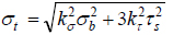 |
(18) |
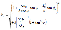
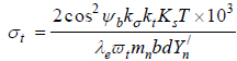
Substitute Eq. (13b) and Eq. (16b) into Eq. (18) and simplify to obtain:
 |
(19) |
where:
 |
(20) |
From Eq. (8) and Eq. (9), it is easy to prove Eq. (21). Eq. (21b) is assumed for simplicity.
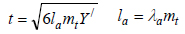 |
(21) |
Eq. (21a) may be expressed as in Eq. (22a) and Eq. (22b) can be deduced.
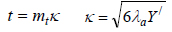 |
(22) |
In Appendix A, a method for estimating λa, using the rack tooth profile is described. It allows a single moment arm factor to be used for a gear profile standard. This is a new concept in gear design.
When Eq. (22a) is substituted in Eq. (20), then Eq. (23) is obtained.
 |
(23) |
Eq. (19) is true for a fictitious spur gear with tangential and axial loads, which are considered as static forces. It needs to be corrected for dynamic load effects. Also, to apply it to an actual helical gear, it must account for the influence of the helix angle.
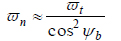
7.1. Accounting for Helix Angle of Helical Gears
The transfer of power between gears in a mesh takes place by means of contact between the active teeth. In helical gears, contact of active teeth occurs in the normal plane. Therefore, the design analysis of helical gears should be preferably done on the normal plane. The normal plane of a helical gear intercepts the pitch cylinder so that the gear tooth profile generated in it has the same properties as the actual helical gear [29H.A. Rortbart, and T.H. Brown, Mechanical Design Handbook., 2nd edMcGraw-Hill: New York, .
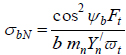
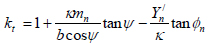
]. The normal plane, therefore, may be used to define an equivalent spur gear for a helical gear. The diameter of the equivalent spur gear depends on the base helix angle because it gives an accurate estimate of the radius of curvature of the equivalent spur gear on the normal plane of contact [28G.M. Maitra, Fundamentals of Toothed Gearing: Handbook of Gear Design., 2nd edMcGraw Hill: New Delhi, pp. 2.82-2.83.]. In helical gears, the normal bending force, acts perpendicular to the tooth similar to the transverse force Ft in spur gears. The analogous bending stress from this force may be expressed using normal plane parameters as was done in a previous work [30E. E. Osakue, and L. Anetor, "Helical gear bending fatigue design", Int’l Journal of Research in Engineering and Technology, vol. 06, no. 04, .]:
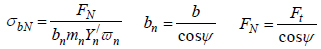 |
(24) |
 |
(25a) |
Substitute Eqs. (24b), (24c), and (25a) in Eq. (24a) to obtain:
 |
(25b) |
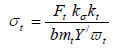
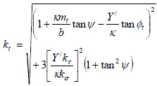
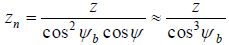
Substitute Ft from Eq. (1b) in Eq. (25) and introduce the stress concentration parameters in Eq. (19) to obtain:
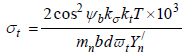 |
(26) |
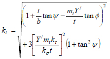
where:
 |
(27) |
Y/n depends on the equivalent number of teeth of a spur gear in the normal plane of a helical gear, as indicated in Eq. (28a) and zn is given by Eq. (28b).
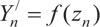 |
(28a) |
 |
(28b) |
Note that ѱ and ѱb are zero, respectively, for spur gears and mn = mt.
Eq. (27) may be used to understand the influence of the radial force component and shear stresses, as indicated in Eq. (29). Eq. (29a) is used when the radial force component is ignored. Eq. (29b) applies when shear stresses are ignored.
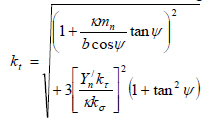 |
(29a) |
 |
(29b) |
7.2. Corrections for Dynamic Load, Mesh Misalignment, and Effective Contact Length
Eq. (26) makes a correction for the helix angle, but the loading is still considered static and ignores friction load effects. Introducing the service load factor into the Lewis model will account for dynamic load and mesh misalignment effects.
Surface roughness seems to have a great influence on the actual contact area when two bodies are in relative sliding motion [31I.V. Kragelskii, Friction and Wear., Butterworths: London, p. 1.]. Factors, such as thermal gradient, centrifugal forces, work hardening, residual stresses [12R.G. Budynas, and J.K. Nissbett, Shigley’s Mechanical Engineering Design, 9th edMcGraw Hill Education: Delhi, pp. 230-232; 293.], etc., can distort pinion or gear shape and lead to teeth mismatch so that full contact does not occur over the nominal face width of meshing gears. In general, the effective face width factor is assumed to account for surface roughness, surface treatment quality, and miscellaneous effects that make contact over the full nominal face width of a gear impossible. AGMA [22AGMA 2001-D04, Fundamental Rating Factors and Calculation Methods for Involute Spur and Helical Gear Teeth:.http://wp.kntu.ac.ir/asgari/AGMA%202001-D04.pdf] suggests a value of 0.95 for the effective face width factor of helical gears; this value is adopted here for spur gears also.
Taking account of the service load factor,Ks and the effective facewidth factor λe; the revised Lewis capacity model for the gear root bending stress of cylindrical gears is:
 |
(30) |
The parameters T, b, d and Y/n in equations (25b) to (30) apply to either the pinion or gear in a mesh. Separate equations for the pinion or gear may be obtained by appending subscript 1 or 2, respectively, to these parameters. It is important to note that the Lewis form factor Y/n is applicable only to standard gears; that is, gears with no profile shift or modification.
7.3. Stress Concentration Factors
Stress concentration gives rise to unusually high stresses near a stress raiser, while much lower values exist on the remainder of the cross-section. Practically, some factors tend to limit stress concentration effects, and these include local plastic deformation, residual stresses, notch radius, component size, and load type. To account for these influences, the ideas of notch sensitivity and effective stress concentration were introduced [19Stress Concentration Factors and Notch Sensitivity.https://moodlearn.ariel.ac.il/pluginfile.php/456050/mod_resource/content/0/Stress-consentration.pdf]. Notch sensitivity is a material’s response to stress concentration, and it is assessed by the notch sensitivity factor that has values between 0 for complete insensitivity and 1 for perfect sensitivity.
Due to the notch sensitivity of materials, the effective stress concentration factor is less than the theoretical value. Eq. (31) defines the relationship between these parameters.
 |
(31) |
According to Zahavi [32E. Zahavi, The Finite Element Method in Machine Design., Prentice-Hall: Eaglewood Cliffs, New Jersey, pp. 232-233.], the theoretical bending stress concentration factor in (steel) gears is in the range from 1.5 to 1.7. For steel gear materials, it is reasonable to expect normal notch sensitivity values in the range of 0.80 for normalized materials to 0.95 for quenched and tempered materials. Applying Eq. (31) to Zahavi’s findings [32E. Zahavi, The Finite Element Method in Machine Design., Prentice-Hall: Eaglewood Cliffs, New Jersey, pp. 232-233.], the effective bending or normal stress concentrator factor would be in the range of 1.4 to 1.67 for steel gears. A bending stress concentration factor of 1.4 is used in a Japanese standard [33KHK, https://khkgears.net/new/gear_knowledge/gear_technical_reference/bending-strength-of-spur-and-helical-gears.html] for steel gear materials. MITCal [34MITCal, Involute Gearing-Theory.www.mitcalc.com/doc/gear1/help/en/gear_theory.htm] used a bending stress concentration factor of 1.5 in some gear design examples. According to Dobrovolsky et al. [11Z.K. Dobrovolsky, S. Mak, A. Radchik, and L. Erlikh, Machine Elements., Foreign Language Pub. House: Moscow, pp. 33-34, 279-289.], the normal stress concentration factor is approximately 1.1 to 1.7 for steel gears and 1.2 for cast iron gears. Therefore, the estimates of the effective normal stress concentration factor in the range from 1.4 to 1.67 seem reasonable for steel gears.
The effective shear stress concentration is taken as 1.7 to 2.2 for flexible spline or harmonic gear teeth generated with pinion cutter and 1.6 to 2.0 when the teeth are hobbed [35D. Chernilevsky, A Practical Course in Machine Design., MIR: Moscow, p. 93.]. Harmonic gear teeth are produced with hobbing and shaping methods, similar to those of cylindrical gears. Based on the above information and using engineering judgment, Table 1 is suggested for use in gear bending stress estimation during initial sizing. The values of the stress concentration factors in the table have no relationship with the point of load application on a gear tooth. The entries for case-hardened steel gears are for surface root bending stress and are informed by the beneficial effects of compressive surface residual stresses they generate. For subsurface root stress, values for quenched and tempered steels may be used.

When values of stress concentration factors in Table 3 are used in Eq. (27), Eq. (29), and Eq. (30), the stress concentration factor is independent of the point of load application on the gear tooth. This eliminates the weaknesses highlighted about the AGMA model, whose stress concentration factor depends on the point of load application on the gear tooth.
8. DESIGN EXAMPLES
The new design formulas presented in the previous sections are applied in four design examples, taken from the indicated references. The problem statements in the design cases have been paraphrased and the design parameters have been converted to metric units where necessary by the authors. The equations presented were coded in Microsoft Excel for computational efficiency. The goal is to estimate the root bending stresses using the new formulae and make comparisons with those from AGMA. AGMA standards are perhaps the most popular gear standards in use and have a good reputation amongst gear designers and manufacturers.
8.1. Design Problems
The four of the design problems are considered below. The solutions to the problems are available from the stated references and comparisons will be made with the estimates from the formulae presented in the sections above. The problems cover a wide range of helix angles, which span from 00 to 41.410. Note that the 00 helical gear is actually a spur gear.
8.1.1. Example 1
A gearset of steel and ductile cast iron transmits a torque of 1694.8 nm at the pinion at 406 rpm. The gearset basic size data are: z1 = z2 = 20, d1 = d2 = 127 mm, b = 25.4 mm. The gearset has a normal pressure angle of 20° and a helix angle of 0°. What is the expected root bending stress? This example was presented in a previous study [21E. Edward, "Osakue, Simplified Spur Gear Design", Proceedings of International Mechanical Engineering Congress and Exposition 2016 IMECE.].
8.1.2. Example 2
A helical steel gearset for a milling machine drive is to transmit 48.5 kW from an electric motor with a pinion speed of 3450 rpm and a gear speed of 1100 rpm. The gearset has a normal pressure angle of 20o and a helix angle of 15o. The pinion has 24 teeth, gear has 75 teeth, the normal module is 2.17 mm and the face width is 57.15 mm. Determine the root bending stress on the pinion [6R.L. Mott, Machine Elements in Mechanical Design, 4th edSI, Pearson Prentice Hall, New York, . Chap., pp. 461 - 462].
8.1.3. Example 3
A 17-tooth helical steel pinion with a right-hand helix angle of 30o rotates at 1800 rpm when transmitting 3 kW to a 52-tooth helical steel gear. The gearset has a normal pressure angle of 20o, normal module of 2.54 mm, and a face width of 38.1 mm. Determine the root bending stress on the pinion [12 pp. 771 – 773].
8.1.4. Example 4
A 15-tooth helical steel pinion with a right-hand helix angle of 41.41o rotates at 2500 rpm when transmitting 3.75 kW to a 24-tooth helical steel gear. The gearset has a normal pressure angle of 20o, normal module of 2.54 mm, and a face width of 29.21 mm. Determine the root bending stress on the pinion [3J.A. Collins, H. Busby, and G.H. Staab, Mechanical Design of Machine Elements and Machines: A Failure Prevention Perspective., 2nd edJohn Wiley and Sons: New York, .
, pp. 658 – 662].
8.2. Solutions to Problems
Table 2 summarizes the basic gearset dimensions and load data, for example, 1 to 4. The service load factors were evaluated and used for root bending stress estimation. Table 3 gives the results for the problems for the revised Lewis model. The entries in the “A” column are obtained from Eq. (27) and Eq. (30). The entries in the “B” column are obtained from Eq. 29a and Eq. (30). The entries in the “C” column are obtained from Eq. 29b) and Eq. (30). Table 4 shows the AGMA bending stress solutions being compared with the revised Lewis model. The stress concentration values used in the bending stress estimations were taken from Table 3.

9. DISCUSSION
The examples cover a wide range of helix angles from 0o to 41.41o. This range essentially covers values in the common practice of cylindrical gear design and manufacture. The influence of the helix angle is directly indicated in equation (30) through the base helix angle. However, the stress correction factor kt also indicates a secondary influence of the helix as revealed in (Eq. (27). The solution of Eq. (30) is unique when compared with current gear design standards. For instance, a different chart is not required for the helix angle factor, as is done in the AGMA approach.
Table 3 gives the results for the new revised Lewis model. Column“A” entries are the new accepted solutions that take account of both the radial load and shear stresses. Column “B” entries ignore the radial load but account for shear stresses. Column “C” entries account for the radial load but ignore shear stresses. The “B-DEV” column shows the percentage deviation of the “B” column from the “A” column. This column shows that the root bending stress is over-estimated by 4.66 to 5.73%, with an average of 5.27%. The “C-DEV” column shows the percentage deviation of the “C” column from the “A” column. This column shows that the root bending stress is under-estimated by 6.67 to 8.16%, with an average of 7.49%. Clearly the influence of shear stresses is important if a more accurate model is desired in root bending stress estimation.
Table 4 shows the bending stresses for comparison purposes. The AGMA values are given in column 3 and column 4 gives values for the revised Lewis formula. Column 5 shows the percentage deviations of the new solutions form the AGMA values in the range of -4.83% to 26.61%. It should be noted that getting accurate values of AGMA-J factor for helical gears is somewhat challenging. The new model solutions are thus, somewhat conservative compared with AGMA results but indicate good comparison.
CONCLUSION
A new revised Lewis bending stress capacity model is formulated and provides a single expression (Eq. (30)) for both spur and helical gears and normal and high contact ratio cylindrical gears. It accounts for both radial compressive stress and shear stresses in cylindrical gearsets. Also, the helix angle is expressly taken into account in Eq. (30) and Eq. (27). Note that a spur gear is a special case of a helical gear when the helix angle is 0o. Eq. (27) and Eq. (30) eliminate the use of multiple charts or tables in estimating root bending stress of thecylindrical gears. The equations use stress concentration factors that are independent of the point of load application on the gear tooth. This brings bending stress analysis in gear design in agreement with classical bending stress analysis of straight and curved beams. Also, the need to identify HPSTC is eliminated and the estimation of Lewis form factor is easier. Load shearing is uniformly applied to both spur and helical gears through the parameter . The use of the rack profile for a gear profile standard in the determination of the moment arm is a new concept introduced in this study. It allows a single moment arm factor to be used for all modules in a gear profile standard. These features make the new model unique from those of AGMA and ISO.
Four design examples of bending stress evaluations with helix angles from 00 to 41.410 were considered. The torque range is 14 to 1695 nm and the estimated root bending stress range is from 27 to 882 MPa. Though higher torques may occur in practice, the stress of 882 MPa is too high and likely unacceptable, since most steel gears would not be able to sustain such a stress value for long. The study results from the new model show that ignoring the radial load led to an over-estimation of 5.27% in the root bending on the average. When shear stresses are ignored, an under-estimation of 7.49% in the root bending on the average was obtained. Accounting for shear stresses is, thus, very important. The root bending stress estimates from the new model for four gearsets were compared with the AGMA results. The differences between the two estimates are in the range of -4.83 to 26.61%. Because gear design is complicated, the design procedures are usually not precise [36Introduction and Perspectives, https://www.asminternational.org/documents]. Hopefully, this study should help improve the accuracy of root bending stress estimation for cylindrical gears.
NOMENCLATURE
| 1, 2 | = subscript for pinion and gear, respectively |
| A1 | = non-elastic misalignment constant |
| A2 | = first order non-elastic misalignment coefficient |
| A3 | = second order non-elastic misalignment coefficient |
| α1 | = internal overload exponent |
| α2 | = internal overload coefficient |
| b | = nominal facewidth of pinion or gear (mm) |
| b1 | = facewidth of pinion (mm) |
| b2 | = facewidth of gear (mm) |
| bn | = nominal gear facewidth in normal plane (mm) |
| Cmn | = non-elastic deformation coefficient |
| Cmc | = gear crowning coefficient |
| Cmg | = gear profile compatibility coefficient |
| Cme | = elastic deformation coefficient |
| Cmp | = gear position location coefficient |
| d | = pitch diameter of pinion or gear (mm) |
| d1 | = pitch diameter of pinion or gear (mm) |
| d2 | = pitch diameter of gear (mm) |
| d/ | = pitch diameter of basic spur pinion or gear (mm) |
| dn | = pitch diameter of equivalent spur pinion or gear (mm) |
| Fr | = nominal radial force (N) |
| Ft | = nominal tangential force (N) |
| Fa | = nominal axial force (N) |
| Fn | = nominal normal contact force (N) |
| FN | = normal plane nominal bending force (N) |
| FN | = normal plane nominal bending force (N) |
| Kδ | = effective normal stress concentration factors |
| K/δ | = effective normal stress concentration factors |
| K/T | = theoretical shear stress concentration factor |
| Kt | = stress correction factor for root tensile stress |
| KS | = service load factor |
| Ka | = application or external overload factor |
| Kv | = internal overload or dynamic factor |
| Kvs | = basic internal overload or dynamic factor |
| Km | = mounting or mesh overload factor |
| Kms | = basic mounting or mesh overload factor |
| Kr | = rim backup factor. |
| KO | = frictional load factor |
| L | = shaft span (mm) |
| K1 | = half-length of shaft span (mm) |
| K2 | = gearset distance form shaft mid-span (mm) |
| la | = bending moment arm (mm) |
| mn | = gear normal module (mm) |
| mt | = transverse module (mm) |
| N | = rotational speed of pinion or gear (rpm) |
| N1 | = rotational speed of pinion (rpm) |
| P1 | = power at pinion (kW) |
| qδ | = material normal stress notch sensitivity factor |
| qT | = material shear stress notch sensitivity factor |
| qn | = AGMA/ISO gear profile quality number |
| t | = gear root thickness (mm) |
| T | = torque load on pinion or gear (Nm) |
| T1 | = torque load on pinion (Nm) |
| T2 | = torque load on gear (Nm) |
| Vt | = pitch point tangential velocity (m/s) |
| VS | = sliding velocity (m/s) |
| Y/ | = Lewis bending stress form factor |
| Y | = modified Lewis bending stress form factor |
| Y/n | = Lewis bending stress form factor in normal plane |
| Zt | = section modulus of gear tooth for transverse plane |
| Za | = section modulus of gear tooth for axial plane |
| z1 | = number of teeth on pinion |
| z2 | = number of teeth on gear |
| zn | = number of teeth on pinion or gear in normal plane |
| λa | = bending moment arm factor |
| λb | = gaer facewidth factor or gear aspect ratio |
| K | = root thickness factor |
| φα | = contact angle at tip of gear (deg.) |
| φn | = normal pressure angle (deg.) |
| φt | = transverse pressure angle (deg.) |
| ѱ | = helix angle (deg.) |
| ѱb | = base helix angle (deg.) |
| δbt | = root bending stress from tangential force (MPa) |
| δba | = bending stress from axial force (MPa) |
| δcr | = compressive stress from radial force (MPa) |
| δb | = compressive stress from radial force (MPa) |
| δbN | = bending stress in normal plane (MPa) |
| δt | = equivalent tensile stress at root of gear (MPa) |
| Tst | = direct shear stress from tangential force (MPa) |
| Tsa | = direct shear stress from axial force (MPa) |
| Ts | = combined direct shear stress at gear root (MPa) |
 n n |
= contact ratio in normal plane |
| t |
= contact ratio in transverse |
| ℓt | = effective gear mesh friction coefficient |
ETHICS APPROVAL AND CONSENT TO PARTICIPATE
Not applicable.
HUMAN AND ANIMAL RIGHTS
Not applicable.
CONSENT FOR PUBLICATION
Not applicable.
AVAILABILITY OF DATA AND MATERIALS
The authors confirm that the data supporting the findings of this study are available within the article.
FUNDING
No grant money from private or public sources or any other funds were used in the research work presented.
CONFLICT OF INTEREST
The author declares no conflict of interest, financial or otherwise.
ACKNOWLEDGEMENTS
This study was supported with research facilities from the College of Science, Engineering and Technology (COSET) and the University Faculty Development unit of Texas Southern University.
APPENDIX A: BENDING MOMENT ARM FACTOR
A diagram of the bending stress form factor curves [33KHK, https://khkgears.net/new/gear_knowledge/gear_technical_reference/bending-strength-of-spur-and-helical-gears.html] for different addendum correction factors converge to one point for a rack tooth. This indicates that the bending stress form factor for a rack is independent of the amount of addendum correction applied to the gear tooth. Now the rack tooth profile envelops all possible involute gear tooth shapes for a tooth standard and hence has a fixed tooth width at the root where the maximum tensile stress occurs. These reasons suggest that the bending moment arm factor λa may be estimated reliably by considering the basic rack profile of a gear tooth system.
Fig. (A1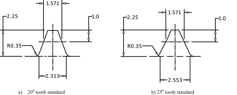 ) shows the basic rack profile for 200 and 250 involute gear tooth standards. The fillet radius factor of 0.35 is a popular value in AGMA recommendations [13R.C. Juvinall, and K.M. Marshek, Juvinall’s Fundamentals of Machine Component Design, S.I.
Version, Wiley: Singapore, p. 282.]. The root thickness is defined at the intersection of the fillet radius and the straight flank line of the rack tooth. A direct measurement of the root thickness which is equal to K for a module of 1 mm (Eq. 22a), can be made from these diagrams. Note that the fillet is tangential to both the straight flank line and the root or deddendum circle horizontal line shown as hidden line. Eq. (A1) is obtained from Eq. (22b).
) shows the basic rack profile for 200 and 250 involute gear tooth standards. The fillet radius factor of 0.35 is a popular value in AGMA recommendations [13R.C. Juvinall, and K.M. Marshek, Juvinall’s Fundamentals of Machine Component Design, S.I.
Version, Wiley: Singapore, p. 282.]. The root thickness is defined at the intersection of the fillet radius and the straight flank line of the rack tooth. A direct measurement of the root thickness which is equal to K for a module of 1 mm (Eq. 22a), can be made from these diagrams. Note that the fillet is tangential to both the straight flank line and the root or deddendum circle horizontal line shown as hidden line. Eq. (A1) is obtained from Eq. (22b).
 |
(A1) |
The value of Y/ for a rack tooth is required in Eq. (A1). In Table A1, column 2 shows Y/ values for some popular involute gear tooth standards. The values of K in the same table are obtained from Fig. (A1). The forth column in the table gives the values of λa for 20° and 25° involute gear tooth standards based on Eq. (A1).
 |
Fig. (A1) Basic rack profile for 20° and 25° involute gear tooth standards. |
APPENDIX B: SERVICE LOAD FACTOR ESTIMATION
The service load factor accounts for the fact the forces acting on equipment in service are generally higher than the rated or nominal values in gear drives. It is a load magnification factor and may be estimated [11Z.K. Dobrovolsky, S. Mak, A. Radchik, and L. Erlikh, Machine Elements., Foreign Language Pub. House: Moscow, pp. 33-34, 279-289., 12R.G. Budynas, and J.K. Nissbett, Shigley’s Mechanical Engineering Design, 9th edMcGraw Hill
Education: Delhi, pp. 230-232; 293., 21E. Edward, "Osakue, Simplified Spur Gear Design", Proceedings of International Mechanical Engineering Congress and Exposition 2016 IMECE., 22AGMA 2001-D04, Fundamental Rating Factors and
Calculation Methods for Involute Spur and Helical Gear Teeth:.http://wp.kntu.ac.ir/asgari/AGMA%202001-D04.pdf, 23E. E. Osakue, and L Anetor, "Design of straight bevel gear for pitting resistance", FME Transactions, vol. 2, pp. 194-204.
[http://dx.doi.org/10.5937/fmet1802194O] , 33KHK, https://khkgears.net/new/gear_knowledge/gear_technical_reference/bending-strength-of-spur-and-helical-gears.html, 37E.E. Osakue, L. Anetor, and K. Harris, "A Parametric Study of Frictional Load Influence in Spur Gear Bending Resistance", FME Transactions, vol. 48, pp. 294-306.
[http://dx.doi.org/10.5937/fme2002294O] ] as:
 |
(A2) |
Application Overload Factor, Ka
The application overload factor accounts for load increases caused by the power source device and the driven or load device on gear drives. It is indicative of the influences of the accelerations and decelerations of external masses connected to the gear drive. Table A2 is an example of values for this factor for 8 to10 hrs of daily operation of a gear drive.

Application Overload Factor (Ka), [6R.L. Mott, Machine Elements in Mechanical Design, 4th edSI, Pearson Prentice Hall, New York, . Chap.].
Internal Overload Factor, Kv
The internal overload factor, KV accounts for load excitations caused by non-conjugate action, backlash, profile error, pitch error, dynamic imbalance, etc. of meshing gears
The internal overlad factor may be estimated using Eq. (A3a) for spur gears and Eq. (A3b) for helical gears.
 |
(A3) |
According to AGMA recommendation [ 22AGMA 2001-D04, Fundamental Rating Factors and Calculation Methods for Involute Spur and Helical Gear Teeth:.http://wp.kntu.ac.ir/asgari/AGMA%202001-D04.pdf]:
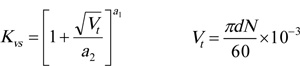 |
(A4) |
Parameters a1 and a2 depend on AGMA gear quality numbers that range from 0 to 12, and are similar to ISO quality numbers. Gear hobbing can produce 7 to 10 gear quality numbers, shaved gears may have 6 to 8 quality numbers, and ground gear can have 2 to 7 quality numbers. Careful production practice can improve on quality numbers. Lower numbers represent higher gear quality. For AGMA/ISO gear quality numbers in the range of 6 ≤ qn ≤ 12:
 |
(A5) |
An estimate of Kv above 1.5 should be considered as probably unacceptable [23E. E. Osakue, and L Anetor, "Design of straight bevel gear for pitting resistance", FME Transactions, vol. 2, pp. 194-204.
[http://dx.doi.org/10.5937/fmet1802194O] ]. For uni-directional loading and as a guide for gear tooth profile quality selection, commercial quality gears may have 1.25, < Kv <1.5 premium quality gears may have 1.15 ≤ Kv <1.5, and precision quality gears may have Kv <1.15. For high speed applications, especially those above 20 m/s, methods that account for gear material properties, mass and inertia of the gears, and actual tooth profile errors should be used to estimate Kv.
Mesh Overload Factor, Km
The mesh or mounting overload factor Km takes care of non-uniform load distribution along the tooth facewidth. The AGMA method presented here is recommended for normal, relatively stiff gear assemblies. It is limited to straddle mounted gears, gear aspect ratio of λb ≤ 2.0, gear face width, b ≤ 1000 mm (40”), and assumes full mesh contact over the face of narrowest gear.
The mesh overload factor may be estimated using Eq. (A6a) for spur gears and Eq. (A6b) for helical gears.
 |
(A6) |
Based on AGMA recommendation [12R.G. Budynas, and J.K. Nissbett, Shigley’s Mechanical Engineering Design, 9th edMcGraw Hill Education: Delhi, pp. 230-232; 293., 22AGMA 2001-D04, Fundamental Rating Factors and Calculation Methods for Involute Spur and Helical Gear Teeth:.http://wp.kntu.ac.ir/asgari/AGMA%202001-D04.pdf]:
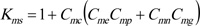 |
(A7) |
Cmn accounts for misalignment of gear pitch cylinders due to non-elastic deformations, principally influenced by the quality of gear mounting. It is evaluated as:
 |
(A8) |
Table A3 gives the values of the coefficients A 1 , A 2 , and A 3 .

Table A3 : Mounting Face-Width Factor Coefficients, [ 12R.G. Budynas, and J.K. Nissbett, Shigley’s Mechanical Engineering Design, 9th edMcGraw Hill Education: Delhi, pp. 230-232; 293.].
Cme accounts for misalignment of gear pitch cylinders due to elastic deformation of shaft, housing, etc. It is a function of the gear aspect ratio and gear face width. Eq. (9) and Eq. (A10) are for λb and Cme, respectively.
 |
(A9) |
Based on the range of values for the gear facewidth, then:
 |
(A10a) |
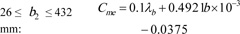 |
(A10b) |
 |
(A10c) |
Eq. (A10) assumes λb = 0.5 when λb < 0.5.
Cmp makes correction for the location of a gearset on a shaft relative to the mid-span. It’s value is based on λP and Fig. (A2 ) indicates how it is evaluated. That is:
 |
(A11) |
Other coefficients in Eq. (A7) are given in Table A4 .
Table A4 : Other Mesh Overload Factor Coefficients, [ 12R.G. Budynas, and J.K. Nissbett, Shigley’s Mechanical Engineering Design, 9th edMcGraw Hill Education: Delhi, pp. 230-232; 293. ].
Eq. (A7) does not apply to cantilever mounted gears. Based on limited data [11Z.K. Dobrovolsky, S. Mak, A. Radchik, and L. Erlikh, Machine Elements., Foreign Language Pub. House: Moscow, pp. 33-34, 279-289., 33KHK, https://khkgears.net/new/gear_knowledge/gear_technical_reference/bending-strength-of-spur-and-helical-gears.html], a conservative estimate of Kms for cantilever mounted gears, is:
 |
(A12 ) |
 |
Fig. (A2) Straddle mounted pinion configuration. |
Rim Rigidity Factor, Kr
This factor accounts for gear tooth base flexibility which is assumed rigid in Lewis’s formulation. Based on AGMA recommendation [ 22AGMA 2001-D04, Fundamental Rating Factors and Calculation Methods for Involute Spur and Helical Gear Teeth:.http://wp.kntu.ac.ir/asgari/AGMA%202001-D04.pdf ], it is evaluated as a function of the gear rim thickness ratio and obtained as:
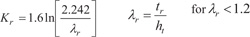 |
(A13) |
 |
(A14) |
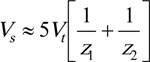
Frictional Load factor
From [
37E.E. Osakue, L. Anetor, and K. Harris, "A Parametric Study of Frictional Load Influence in Spur Gear Bending Resistance", FME Transactions, vol. 48, pp. 294-306.
[http://dx.doi.org/10.5937/fme2002294O]
], the frictional load factor for enclosed gear drives may be approximated as:
 |
(A15) |
Where:
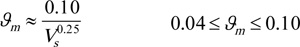 |
(A16) |
and:
 |
(A17) |
Eq. (A17) is useful during design verification or validation when the gearset is already sized. During initial sizing of gears, the gear dimensions are unknown, hence Vt, Vs and ℓm cannot be evaluated. Therefore, a value of 1.1 is suggested for K0 in enclosed gear drives and 1.15 is suggested for open gear drives during initial sizing of cylindrical gears.
REFERENCES
| [1] | Spur Gear Terms and Concepts.http://www.gearseds.com/files/6.3.1 _Gear_Terms_Lesson_rev3.pdf |
| [2] | R.S. Khurmi, and J.K. Gupta, A Textbook of Machine Design., Eurasia Publishing House: New Delhi, p. 1066. |
| [3] | J.A. Collins, H. Busby, and G.H. Staab, Mechanical Design of Machine Elements and Machines: A Failure Prevention Perspective., 2nd edJohn Wiley and Sons: New York, . |
| [4] | J.R. Partridge, High Speed Gears-Design and Applications.http://turbolab.tamu.edu/proc/turboproc/T6/T6pg133-142.pdf |
| [5] | A. Y. Gidado, I. Muhammad, and A. A. Umar, "Design, modeling and analysis of helical gear according to bending strength using AGMA and ANSYS", Int’l Journal of Engineering Trends and Technology, vol. 8, no. 9, . |
| [6] | R.L. Mott, Machine Elements in Mechanical Design, 4th edSI, Pearson Prentice Hall, New York, . Chap. |
| [7] | E. Bergseth, Influence of Gear Surface Roughness, Lubricant Viscosity and Quality Level on ISO 6336 Calculation of Surface Durability, .Technical Report, Department of Machine Design, Royal Institute of Technology, Stockholm, https://www.diva-portal.org/smash/get/diva2:489751/FULLTEXT01.pdf |
| [8] | S.R. Schmid, B.J. Hamrock, and B.O. Jacobson, Fundamentals of Machine Elements., 3rd edCRC Press: New York, . [http://dx.doi.org/10.1201/b17120] |
| [9] | V.S.N.K. Bommisetty, Finite element analysis of spur gear set, masters, Thesis, Mechanical Engineering Department, Cleveland State University, . |
| [10] | A. Kawalec, J. Wiktor, and D. Ceglarek, "Comparative analysis of tooth-root strength using iso and agma standards in spur and helical gears with fem-bases verification", J. Mech. Des., vol. 128, pp. 1141-1158. [http://dx.doi.org/10.1115/1.2214735] |
| [11] | Z.K. Dobrovolsky, S. Mak, A. Radchik, and L. Erlikh, Machine Elements., Foreign Language Pub. House: Moscow, pp. 33-34, 279-289. |
| [12] | R.G. Budynas, and J.K. Nissbett, Shigley’s Mechanical Engineering Design, 9th edMcGraw Hill Education: Delhi, pp. 230-232; 293. |
| [13] | R.C. Juvinall, and K.M. Marshek, Juvinall’s Fundamentals of Machine Component Design, S.I. Version, Wiley: Singapore, p. 282. |
| [14] | V. Rudnev, Residual stresses in induction hardening: Simply Complex., Heat Treating Progress, pp. 27-28. |
| [15] | M. Roux, R. Zeng, R. Wilmes, and K. Y. Kim, "Remediation of lost compressive residual stresses in carburized steel gears", Materials Engineering, Purdue. |
| [16] | B. LeMaster, J. Boggs, C. Hubbard Bunn, and T. Watkins, "Grinding Induced Changes in Residual Stresses of Carburized Gears", Gear Technology, pp. 42-49. |
| [17] | D.W. Dudley, Handbook of Practical Gear Design, CRC Press: Baca Raton, pp. 2.10-2.11. |
| [18] | J.E. Shigley, and C.R. Mischke, Standard Handbook of Machine Design, McGraw-Hill, New York, . Chap 13. |
| [19] | Stress Concentration Factors and Notch Sensitivity.https://moodlearn.ariel.ac.il/pluginfile.php/456050/mod_resource/content/0/Stress-consentration.pdf |
| [20] | E. E. Osakue, and L. Anetor, "Helical Gear Contact Fatigue Design by Spur Gear Equivalency", Int’l Journal of Research in Engineering and Technology, vol. 06, no. 02, . |
| [21] | E. Edward, "Osakue, Simplified Spur Gear Design", Proceedings of International Mechanical Engineering Congress and Exposition 2016 IMECE. |
| [22] | AGMA 2001-D04, Fundamental Rating Factors and Calculation Methods for Involute Spur and Helical Gear Teeth:.http://wp.kntu.ac.ir/asgari/AGMA%202001-D04.pdf |
| [23] | E. E. Osakue, and L Anetor, "Design of straight bevel gear for pitting resistance", FME Transactions, vol. 2, pp. 194-204. [http://dx.doi.org/10.5937/fmet1802194O] |
| [24] | K. Gopinath, and M.M. Mayuram, Machine Design II, Module 2 – GEARS, Lecture 7 - SPUR GEAR DESIGN.https://nptel.ac.in/courses/112106137/pdf/2_7.pdf |
| [25] | MECH 344:, Machine Element Design, Lecture 11.https://users.encs.concordia.ca/~nrskumar/Index_files/Mech344/Lectures/Lecture_11.pdf |
| [26] | M. Petrov, D. Chernilevsky, and Y. Berezovsky, Machine Design., MIR: Moscow, pp. 137-139. |
| [27] | Design for Strength, Lewis Bending Equation.https://images.search.yahoo.com/yhs/search |
| [28] | G.M. Maitra, Fundamentals of Toothed Gearing: Handbook of Gear Design., 2nd edMcGraw Hill: New Delhi, pp. 2.82-2.83. |
| [29] | H.A. Rortbart, and T.H. Brown, Mechanical Design Handbook., 2nd edMcGraw-Hill: New York, . |
| [30] | E. E. Osakue, and L. Anetor, "Helical gear bending fatigue design", Int’l Journal of Research in Engineering and Technology, vol. 06, no. 04, . |
| [31] | I.V. Kragelskii, Friction and Wear., Butterworths: London, p. 1. |
| [32] | E. Zahavi, The Finite Element Method in Machine Design., Prentice-Hall: Eaglewood Cliffs, New Jersey, pp. 232-233. |
| [33] | KHK, https://khkgears.net/new/gear_knowledge/gear_technical_reference/bending-strength-of-spur-and-helical-gears.html |
| [34] | MITCal, Involute Gearing-Theory.www.mitcalc.com/doc/gear1/help/en/gear_theory.htm |
| [35] | D. Chernilevsky, A Practical Course in Machine Design., MIR: Moscow, p. 93. |
| [36] | Introduction and Perspectives, https://www.asminternational.org/documents |
| [37] | E.E. Osakue, L. Anetor, and K. Harris, "A Parametric Study of Frictional Load Influence in Spur Gear Bending Resistance", FME Transactions, vol. 48, pp. 294-306. [http://dx.doi.org/10.5937/fme2002294O] |