- Home
- About Journals
-
Information for Authors/ReviewersEditorial Policies
Publication Fee
Publication Cycle - Process Flowchart
Online Manuscript Submission and Tracking System
Publishing Ethics and Rectitude
Authorship
Author Benefits
Reviewer Guidelines
Guest Editor Guidelines
Peer Review Workflow
Quick Track Option
Copyediting Services
Bentham Open Membership
Bentham Open Advisory Board
Archiving Policies
Fabricating and Stating False Information
Post Publication Discussions and Corrections
Editorial Management
Advertise With Us
Funding Agencies
Rate List
Kudos
General FAQs
Special Fee Waivers and Discounts
- Contact
- Help
- About Us
- Search


The Open Petroleum Engineering Journal
(Discontinued)
ISSN: 1874-8341 ― Volume 12, 2019
Experimental Study of Self-aggregating Proppants: New Approaches to Proppant Flowback Control
Lipei Fu, Guicai Zhang*, Jijiang Ge, Kaili Liao*, Haihua Pei, Jianda Li
Abstract
Due to the high rate of proppant flowback after hydraulic fracturing stimulations, surface modified quartz sand proppants with excellent proppant flowback control abilities, self-aggregating proppants, were prepared. These surface modified proppants can aggregate together spontaneously and form a proppant column in water based liquid environment. Analyses show that the strong hydrogen bonds contribute to the absorption of the surface modifier onto the proppants, and the softening effect of the water to the polymer coating prompts the connection between the proppants. Scanning electron microscope pictures show that proppant particles are stacked together tightly. The stable structure contributes to the macroscopic stability of the proppant column. The maximum sand free flow rate of the model packed with modified proppants is 2.8 times larger than that of untreated proppants by average, indicating that the self-aggregating proppants exhibit excellent proppant flowback control abilities. In addition, fines control tests show that the modified proppants can also prevent the migration of the formation fines effectively, reducing the conductivity loss caused by particle migrations. By virtue of the reaggreating property and the encapsulation action of polymer coating to the crushed fragments, the fracture conductivities are increased by 3 times even at large closure stresses. The results provide a new alternative for proppant flowback control while do little damage to the permeability of the proppant pack.
Article Information

Identifiers and Pagination:
Year: 2016Volume: 9
First Page: 236
Last Page: 246
Publisher Id: TOPEJ-9-236
DOI: 10.2174/1874834101609010236
Article History:
Received Date: 02/04/2016Revision Received Date: 6/6/2016
Acceptance Date: 29/6/2016
Electronic publication date: 29/11/2016
Collection year: 2016
open-access license: This is an open access article licensed under the terms of the Creative Commons Attribution-Non-Commercial 4.0 International Public License (CC BY-NC 4.0) (https://creativecommons.org/licenses/by-nc/4.0/legalcode), which permits unrestricted, non-commercial use, distribution and reproduction in any medium, provided the work is properly cited.
* Address correspondence to these authors at the B523, Engineering Building, School of Petroleum Engineering, China University of Petroleum (East China), No. 66 Changjiang West Road, Qingdao, 266580, China; Tel: 15553247997; Fax: 0532-86981178; E-mails: 13706368080@vip.163.com, lkl123@163.com
| Open Peer Review Details | |||
|---|---|---|---|
| Manuscript submitted on 02-04-2016 |
Original Manuscript | Experimental Study of Self-aggregating Proppants: New Approaches to Proppant Flowback Control | |
1. INTRODUCTION
With the further development of the mature oil fields, especially the exploitation of the low permeability and extra-low permeability reservoirs, hydraulic fracturing has become the main and effective reservoir stimulation treatment [1F. Liang, M. Sayed, A. Ghaithan, and F. Chang, "Overview of existing proppant technology and challenges", In: SPE Middle East Oil & Gas Show and Conference, Society of Petroleum Engineers: Manama, Bahrain, 2015.
[http://dx.doi.org/10.2118/172763-MS] ]. In addition, hydraulic fracturing is indispensable with regard to tight oil, shale gas and other unconventional oil and gas resources. Hydraulic fracturing stimulation has made great contributions to oil and gas industry since it was introduced to the field [2M. Zoveidavianpoor, and A. Gharibi, "Application of polymers for coating of proppant in hydraulic fracturing of subterraneous form ations: A comprehensive review", Journal of Natural Gas Science and Engineering, vol. 24, no. 1, pp. 197-209, 2015.
[http://dx.doi.org/10.1016/j.jngse.2015.03.024] ].
The proppant, which is the second amount of the materials used in hydraulic fracturing, is used to keep open of the artificial fracture. After the fracturing fluid is discharged, the proppant pack plays an important role in supporting the fracture, which draws a considerable attention in recent years [3J. Veatch, and Z.A. Moschovidis, "An overview of recent advances in hydraulic fracturing technology", In: International Meeting on Petroleum Engineering, Society of Petroleum Engineers: Beijing, China, 1986.
[http://dx.doi.org/10.2118/14085-MS] ]. There are lots of actual problems associated with proppants. The changes in the formation stress cause fatigue of the proppant pack, and lead to proppants breakage and fines emission, which are harmful to the fracture conductivity. The fracture conductivity reduces by 60 percentages if the amount of fines migration is up to 5%. Scaling always comes together with proppants, because of the hydrophilic characteristic of the common propping materials [4Q. Wu, Y. Xu, X.Q. Wang, T.F. Wang, and S.L. Zhang, "Volume fracturing technology of unconventional reservoirs-connotation, optimization design and implementation", Petroleum Exploration and Development, vol. 39, no. 1, pp. 352-358, 2012.].
However, the most serious problem that the proppant technology faces is the proppant flowback, which is the combined result of many factors, such as the changes in reservoir conditions, the property of the proppants, the physical properties of the working fluids, and the large drag forces of the oil and gas with high production flow rate. Sometimes the flowback rate reaches as high as 20% of the total injection, especially in the unconsolidated sandstone formations with low closure stresses and micro fractures. The proppant particles flowing out of the artificial fracture come into the wellbore as well as the surface pipeline. Proppant flowback narrows down the width of the artificial fracture, reducing the effectiveness of the stimulation, even leading to the fracture failure within a short time. In addition, downhole remedial operations, such as sand washing, are needed for wells that encounter with proppant flowback, which could inevitably affect the normal hydrocarbon production. Moreover, the discharged proppants can erode downhole equipments, as well as surface pipelines and equipments, shortening their service lives [5W.M. Zhang, L. Chen, G.P. Ren, J.L. Jie, and W.L. Gao, "Study on procured resin coating sands", Acta Petrol. Sin., vol. 22, no. 1, pp. 75-80, 2006. [Petroleum Processing Section]., 6P.D. Nguyen, J.D. Weaver, and R.D. Rickman, "Remdiation of proppant flowback: Laboratory and field studies", In: SPE European Formation Damage Conference, Scheveningen, The Netherlands, 2007.
[http://dx.doi.org/10.2118/106108-MS] ].
High efficiency gel breaker is introduced to reduce the carrying capacity of the fracturing fluid during its postfrac flowback process. Jiang et al. pointed out that the forced closure technique in fracturing operation ahead of the natural fracture closure is another technique to encapsulate the maximum proppants within the fracture [7T.X. Jiang, X.G. Wang, and W.L. Guan, "A new analytical model for pressure dectine under condition of forced fracture closure", Acta Petrol. Sin., vol. 24, no. 1, pp. 78-81, 2003.]. In addition, adding fibrous materials into the fracturing fluid to enhance the integrity of proppant pack is another effective method to control proppant flowback [8P.R. Howard, M.T. King, and M. Morris, "Fiber/Proppant mixture control proppant flowback in south Texas", In: SPE Annual Technical Conference & Exhibition, Dallas, USA, 1995.
[http://dx.doi.org/10.2118/30495-MS] , 9A. Burukhin, S. Kalinin, and J. Abbott, "Novel interconnected bonded structure enhances proppant flowback control", In: SPE International Symposium and Exhibition on Formation Damage Control, Lafayette, Louisiana, USA, 2012.
[http://dx.doi.org/10.2118/151861-MS] ]. The fibers, which bond proppants together, are thought to provide framework for the particles. However, Jiao pointed out that due to their minor diameter, slender fibers tend to break into smaller fragments which may cause blockage in the process of hydrocarbons productions [10G.Y. Jiao, J.H. Wang, and J.J. Pan, "Mechanism, prediction and control of proppant backflow", West-China Exploration Engineering, vol. 19, no. 4, pp. 64-67, 2007.]. Meanwhile, Nguyen pointed out that the broken fiber fragments lead to a weakened framework for the proppant pack in the fracture [11P.D. Nguyen, J.D. Weaver, and M.A. Parker, "Proppant flowback control additives", In: SPE Annual Technical Conference and Exhibition, Society of Petroleum Engineers: Denver, Colorado, 1996.
[http://dx.doi.org/10.2118/36689-MS] ].
Moreover, resin coated proppant technology was the common method to solve proppant flowback [12P. Creel, K.D. Totty, and B. Crump, "Proppant flowback control", In: SPE 64th Annual Technical Conference and Exhibition, San Antonio, Texas, USA, 1989., 13C. Stanciu, L.K. Vo, P.D. Nguyen, and J.D. Weaver, "Maintaining well productivity through controlling fines migration and scale formation", In: EUROPEC 2015, Society of Petroleum Engineers: Madrid, Spain, 2015.
[http://dx.doi.org/10.2118/174364-MS] ]. During the past decades of development, two main methods were formed and were widely used on site: pre-cured proppants and curable proppants [14C.D. Pope, T.J. Wiles, and B.R. Pierce, "Curable resin-coated sand controls proppant flowback", In: SPE Production Operations Symposium, Oklahoma City, Oklahoma, 1987.
[http://dx.doi.org/10.2118/16209-MS] -16G.Y. Jiao, P.T. Pei, and Z.L. Qi, "The latest development of proppant flowback of fractured gas well", Journal of Chongqing University of Science and Technology (Natural Science Edition), vol. 14, no. 1, pp. 82-84, 2012.]. The pre-cured proppants were coated at the sand plant and transported to the site when used. During the storage and the transportation, a portion of resin is cured, which cannot provide sufficient consolidation strengths for the proppant pack [17Z.J. Zhang, S.B. Zhang, and M.W. Tan, "Laboratory study on fiber enhanced proppant to prevent flwoback after fracturing", Drilling & Production Technology, vol. 28, no. 1, pp. 90-93, 2005.-19U.A. Inyang, P.D. Nguyen, and J. Cortez, "Development and field application of highly conductivity proppant-free channel fracturing method", In: SPE Unconventional Resources Conference, The Woodlands, Texas, USA, 2014.
[http://dx.doi.org/10.2118/168996-MS] ]. Unlike resin pre-coated proppants, liquid resin coating technology injects both curable resin and hardener into the fracture at the end of the stimulation. Large amount of resin is needed, compared with pre-coated proppants [20P.D. Nguyen, J.D. Weaver, R.D. Rickman, and M.W. Sanders, "Application of diluted consolidation systems to improve effectiveness of proppant flowback remediation: Laboratory and field results", In: SPE International Symposium on Oilfield Chemistry, Houston, USA, 2009.
[http://dx.doi.org/10.2118/106105-PA] -22J.C. Zhang, and X.B. Bian, "A comprehensive experimental study for optimization of fracture stabilizers", Fuel, vol. 132, no. 1, pp. 149-152, 2014.
[http://dx.doi.org/10.1016/j.fuel.2014.04.073] ]. Anderson pointed out that the three dimensional network of the phenolic resin improved the properties of the phenolic resin coated proppant, such as imparts the proppant with an ability of temperature resistance, as well as, solvent resistance to hydrofluoric acid and hydrochloric acid, making phenolic resin widely used for proppant modification [23R.W. Anderson, D.E. Johnson, and T. Diep, "New resin technology improves proppant flowback control in HT/HP environments", In: SPE Annual Technical Conference and Exhibiton, San Antonio, Texas, USA, 2002.
[http://dx.doi.org/10.2118/77745-MS] ]. Dewprashad pointed out that the epoxy resin used in LRC exhibiting higher strength was more flexible and resistance to cyclic loading than phenolic resins in most RCP, as well as exhibiting more tolerant of mixing times and exposures to temperatures [24B. Dewprashea, H.H. Abass, and D.L. Meadows, "A method to select resin-coated proppants", In: SPE 68th Annual Technical Conference and Exhibition of the Society of Petroleum Engineers, Houston, Texas, USA, 1993. SPE 26523.]. Nguyen discovered that the thermoplastic coating, like polyethylene, polyimides, and polycarbonates, increased the contact area between proppant particles, induced agglomeration with each other, and helped resist porppant flowback, if the formation temperature was high enough to trigger the softening effect of the thermoplastic coating [25P.D. Nguyen, J.D. Weaver, and M.A. Parker, "Thermoplastic Particles, Ribbons or Flakes", U.S. Patent 5501274, Mar 26, 1996., 26P.D. Nguyen, J.D. Weaver, and M.A. Parker, "Thermoplastic film prevents proppant flowback", Oil Gas J., vol. 94, no. 6, pp. 60-62, 1996.]. Unlike curable resin coated proppants, Nguyen and Weaver introduced a new agglomeration agent that could provide cohesion forces between particles and could not harden or cure under the reservoir conditions. The active ingredient is polyamide copolymer with a molecular weight of 5000 g/mol. The tacky surface of the particles not only decreases the movement of the proppant and fines, but also prevents the scale deposition [27P.D. Nguyen, and J.D. Weaver, "Enhancing well productivity in a tight-gas formation with an aqueous- based, surface-modification agent: Laboratory study", In: SPE Tight Gas Completions Conference, San Antonio, Texas, USA, 2010.
[http://dx.doi.org/10.2118/137136-MS] ]. Although resin coated proppants technology reduces the proppant flowback rate by a large margin, and the proppant pack possesses a high strength for supporting the fracture when the liquid resin is cured, there always exists a big loss in the permeability of the proppant pack.
The aforementioned methods have two shortcomings. One is the damage to the permeability of the proppant pack or to say the conductivity of the fracture. The other is if the closure stress exceeds the strength resistance of the proppants, proppants are crushed to fines. Once proppants or fines flowback occur, the cured resin coating or the fibrous materials are helpless. However, the Weatherford proposed a new point of zeta potential based sand self-aggregating technology, and the coated sands can aggregate several times if the sands aggregates are shaken to strewing sands. The technology has been successfully applied to control formation fines migration [28S. Kakadjian, F. Zamora, and J. Venditto, "Zeta potential altering system for increased fluid recovery, production, and fins control", In: SPE International Symposium on Oilfield Chemistry, Houston, Texas, USA, 2007.] (Kadajian, 2007), reduce the amount of sands production of oil well [29S. Pratyush, and P. Ronvan, "A novel chemical sand and fines control using zeta potential altering chemistry and placement technique", In: SPE International Petroleum Technology Conference, Doha, Qatar, 2014.] (Pratyush, 2014), increase productivity of gas well [30M.G. Jaimes, D. Valencia, and J.I. Bahamon, "Modifying the zeta potential of formation fines utilizing chemical treatment: An alternative to sand control to increase productivity: A Colombian field application", In: SPE Latin American and Caribbean Petroleum Engineering Conference, Maracaibo, Venezuela, 2014.
[http://dx.doi.org/10.2118/169397-MS] ] (Jaimes, 2014), and control proppant flowback [31D.S. Treybig, R. Saini, and L. Vigderman, "Consolidating sand with new generation zeta potential altering systems", In: SPE International Conference & Exhibition on Formation Damage Control, Lafayette, Louisiana, USA, 2016.
[http://dx.doi.org/10.2118/179022-MS] ] (Treybig, 2016). Unlike the concept that altering the zeta potential of the particles, in this study a self-aggregating proppant based on the soften effect of the polymer coating and the intertwining effect of the flexible long-chain groups is introduced to solve proppant flowback. Self-aggregating proppants (SAPs), as its name implies, can aggregate together spontaneously in liquid conditions. There is no permeability loss. It is more important that SAPs can aggregate again if the proppant column is scattered to strewing sands, meaning the fines of crushed proppants can form a new stable column if they contact with SAPs. The mechanism of the surface modification and the aggregating process were illustrated. The maximum sand free flow rate tests were conducted to study the proppant flowback control abilities of SAPs. Fines control tests and fracture conductivity tests were carried out to study the performance in improving the permeability of the proppant pack.
2. EXPERIMENTAL SECTION
2.1. Materials
Chemicals applied in the experiments, such as KCl and methyl alcohol, were all of analytical-grade and purchased from Sinopharm, China. The quartz sand proppants with a size of 20/40 meshes were provided by Juxing Mining Products Plant. The coal fines with a size of 200 meshes were purchased from Zibo Mining Group C., Ltd (Zibo, China). The heterocyclic polymer was synthesized in our laboratory, and the monomer was purchased from Shanghai Xietong Co., Ltd.
2.2. Preparation of Self-aggregating Proppants
The surface modifier is a methyl alcohol solution of heterocyclic polymer with the mass fraction of 25 wt %. The coating processes were carried out at 20°C. First, 20g of the proppants were put into the sand mixer (GJ-3S, Qingdao Jiaonan Analysis Instrument Co., Ltd). 0.8g of the surface modifier was added into the container. The rotary speed of the sand mixing equipment was 100 rmp and the mixing time was 2 minutes. Then the coated quartz sand proppants were removed out of the container, and were put into an evaporating dish for further process. At last, the modified proppants were put into an oven with temperature of 60°C for 2 hours to dry the proppants. After all of the procedures, the dry coated, non-sticky, and strewing quartz sand proppants were obtained.
2.3. Measurement of Fracture Conductivity
The fracture conductivity was measured by the conductivity test instrument designed according to API standard RP 61-1989 “Recommended practices for evaluating short term proppant pack conductivity”, as shown in Fig. (1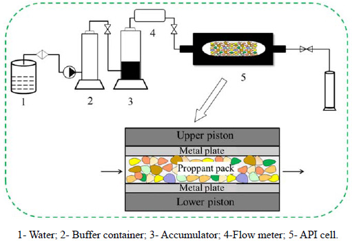 ). In order to obtain more accurate results, each experiment was repeated three times, and the averages of the results were selected. The quartz sand proppants or SAPs were loaded onto the bottom plate at a concentration of 15kg/m2. The closure stress was impose onto the cell. In the entire test, the temperature was 60°C and the injecting fluid was 2 wt % KCl solution. The conductivity of the proppant pack can be calculated through the formula,
 . In which, k is the permeability of proppant pack, μm2; Wf is the width of the proppant pack, cm; k Wf is the conductivity of proppant pack, μm2·cm; μ is the viscosity of the fluid at the test conditions, mPa·s; Q is the flow quantity, cm3/min; Δp is the differential pressure, kPa.
 |
Fig. (1) Schematic layout of fracturing conductivity test instrument. |
2.4. Measurement of Proppant Flowback Control Ability
The maximum sand free flow rate is a common parameter to evaluate the proppant flowback control ability. The fracture conductivity instrument was employed to determine the proppant flowback rate under different closure stresses, and each test was conducted three times. The test method was as follows. The API Cell was loaded with self-aggregating proppants, the closure stress was applied onto the cell, and the stress and the temperature were adjusted to the specified conditions, the parameters of which were consistent with that of the fracture conductivity tests. The KCl solution was used as the formation fluids, flowing through the proppant pack. The closure stress was set and started to inject the KCl solution with an increase rate of the flow rate of 5cm3/min. If proppant particles were observed in the effluent, stop the tests, and the flow rate of the KCl solution was the maximum sand free flow rate under the specific closure stress.
2.5. Measurement of Fines Control Ability
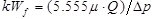
Fine control tests were conducted in a special sand pack model, as shown in Fig. (2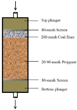 ). From top to bottom, the model included a top plunger, a screen of 80-mesh, a layer of coal fines with a size range from 63μm to 75μm, a layer of self-aggregating proppant pack, the bottom screen and the bottom plunger. In order to simulate the migration of formation fines into the proppant pack, coal fines with the size of 200 meshes were packed after proppants with the size of 20/40 mesh. With this placement, the coal fines were allowed to migrate with the fluid and invade into the proppant pack easily. The whole flooding tests were carried out at 20°C. At the beginning of the tests, in order to saturate the sand pack, the KCl solution was injected from the top of the cell at the flow rate of 5 mL/min for 5 minutes. Then the flow rate was increased at a gradient of 5mL/min until the maximum rate of 100mL/min, and the sand pack was flushed for 10 min under this flow rate. At last, sands were removed out from the sand pack and observed by Smartzoom 5, Carl Zeiss AG, to study the fines control ability of the modified proppants from the microscopic view. For the contol tests, the layer of proppant pack was filled with untreated proppants.
 |
Fig. (2) Schematic of the sand pack for fines control tests. |
3. RESULTS AND DISCUSSION
3.1. Evaluation of Self-aggregating Property
The self-aggregating property of SAPs was qualitatively analyzed by their status in the tube, as shown in Fig. (3 ). The 20g SAPs were poured into a centrifuge tube with the capacity of 100mL, and the tube was filled with the KCl solution. It can be seen that proppant column was formed and dropped down as a whole when the tube was turned upside down (Fig. 3, left). While the untreated proppants were still strewing sands and fell down to the bottom immediately (Fig. 3, right). The experimental phenomenon illustrates that the treated sands can aggregate to proppant column spontaneously. EM-30 of COXEM is used to study the microstructure of the proppant column, as shown in Fig. (4
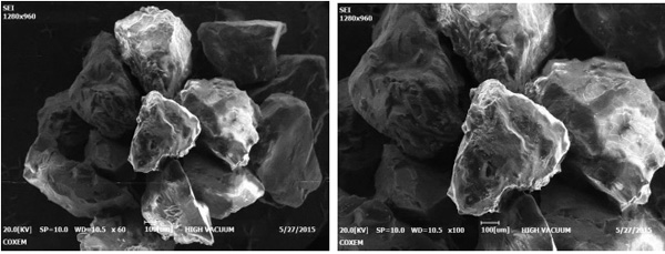 ). The SEM pictures show that proppant particles are stacked together tightly, and stable structure is formed among the grains, with which the aggregated columns can bear large overburden stress.
 |
Fig. (3) Photographs of (left) proppants treated by self-aggregating agent and (right) untreated proppants. |
 |
Fig. (4) SEM pictures of aggregating structure of SIAPs (left: 60×; right: 100×). |
The heterocyclic polymer can be absorbed onto the proppants easily, because there are a large number of nitrogen atoms and fluorine atoms on the heterocyclic polymer both of which can form hydrogen bonds with the silicone hydroxyl on the surface of the quartz sands, as shown in Fig. (5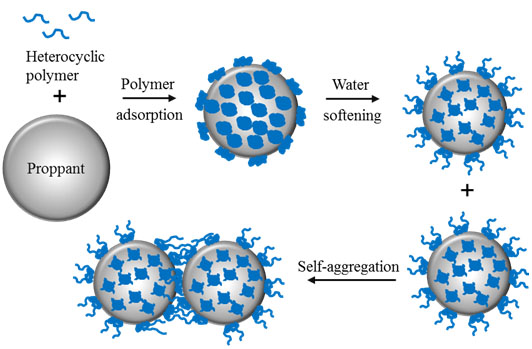 ). The processes of coating and aggregation are illustrated in Fig. (6
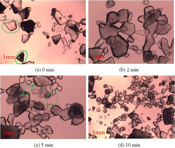 ). After the methyl alcohol is evaporated, the solid coating of the heterocyclic polymer is formed on the surface of the particles. When the surface modified proppants are put into the liquid environment, the softening effect of the water to the polymer changes the surface from the solid coating to flexible long-chain groups. The soften effect can be explained by the shapes and dispersion states of the polymer particles of heterocyclic polymer in distilled water, as shown in Fig. (7
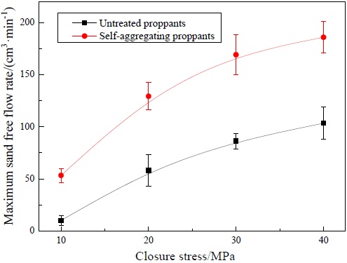 ). At the beginning, the particles are all angular, while the edges disappear after two minutes’ contact with water. With the softening effect of the distilled water, the flexible long-chain groups of heterocyclic polymer were stretched into the distilled water. These particles float on the surface of the water and keep moving irregularly in the form of Brownian movement. If the twisting force of flexible long-chain groups of heterocyclic polymer is high enough to overcome the separation force of Brownian motion, the aggregations between the adjacent particles occur. Oppositely, if the former is smaller than the latter, the contact particles separate again, which can be explained by the broken filament between the particles as shown in Fig. (6c). When the hydration shell is thick enough to release more flexible long-chain groups, more and more particles contact with each other, as shown in Fig. (6d). Therefore, with regard to polymer coated proppants, when the two particles are close to each other, the flexible long-chain groups will come into contact, intertwine again and form a complete structure, leading to the macro performance that a sand column is formed.
 |
Fig. (5) Schematic of the mechanism of self-aggregating proppants. |
3.2. Evaluation of Proppant Flowback Control Property
The maximum sand free flow rates of both SAPs and untreated proppants under different closure stresses are shown in Fig. (7). It can be found that the maximum sand free flow rate of SAPs is higher than that of untreated proppants under every closure stress. In other words, the self-aggregating proppants can reduce the proppant flowback rate effectively. Compared the trends of the two curves, it can be concluded that the higher, the closure stress, the bigger the gaps between them, indicating that the advantages of self-aggregating proppants in proppant flowback control are more obvious under high overburden pressure. That’s because the SAPs can reaggregate again if the proppant column is shocked to strewing sands. Some weakly bonded particles are washed off inevitably, if the fluid flow rate is too large. With the reaggregating property, new connection could be formed between the moving particles and the main part. This reaggregating property plays an important role in maintaining the morphology of the fracture and providing high conductivity for a long period.
 |
Fig. (6) Pictures of the state of heterocyclic polymer particles in distilled water. |
 |
Fig. (7) Maximum sand flow rate at different closure stresses. |
3.3. Evaluation of Fines Control Ability
The effluents of the tests were collected and compared to study the fines migrations. The released liquor of untreated proppants was turbid, and coal fines were suspended in the liquid or absorbed on the bottle walls. While the effluents from sand pack model of self-aggregating proppant were transparent. The proppants were taken out and observed by a digital microscope (Smartzoom5, Carl Zeiss AG, Germany), as shown in Fig. (8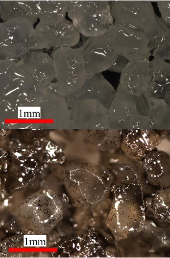 ). It can be found that both the untreated proppants and SAPs particles are moist. Meanwhile, masses of coal fines are captured onto the SAPs. However, the surfaces of the former are clean, and almost no fines are found.
 |
Fig. (8) Pictures of (upper) untreated proppants and (lower) SAPs after fines control tests. |
With this fines control ability, the formation particles peeled and carried by the fluid in hydrocarbon productions, can be absorbed and bonded on the proppant pack. The grains are less likely to move again, which will reduce the risk of seepage channel blockage by a large margin, maintaining a long term of sand-free production and keeping the fracture cleaning with a high conductivity after the hydraulic fracturing treatment.
3.4. Evaluation of Fracture Conductivity
The fracture conductivities of both untreated and self-aggregating proppants at different closure stresses are shown in Fig. (9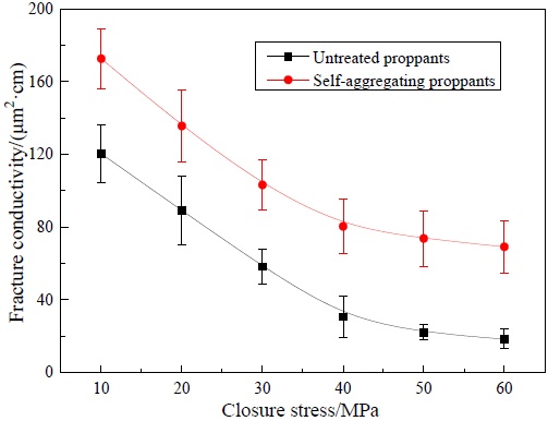 ). At beginning, the SAPs are 1.4 times the conductivity of the untreated proppants. That’s because the column of the self-aggregating proppants itself has a certain strength, which can sustain some overburden pressures, so the SAPs exhibit a bit higher conductivity than the other. With the increase of the closure stress, the conductivity of untreated proppants decreases rapidly. The conductivity is nearly 20 μm2·cm under the closure stress of 60 MPa, while the conductivity of SAPs is almost 70 μm2·cm which is 3.8 times larger than that of the former.
 |
Fig. (9) Fracture conductivity at different closure stresses. |
This experimental phenomenon can be explained from two aspects. On the one hand, when the fracture closure stress exceeds the strength of the proppants, the particles are crushed along the axial stress. The fines are released when the proppants are shattered (Fig. 10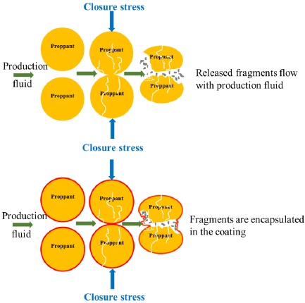 , upper) [2M. Zoveidavianpoor, and A. Gharibi, "Application of polymers for coating of proppant in hydraulic fracturing of subterraneous form ations: A comprehensive review", Journal of Natural Gas Science and Engineering, vol. 24, no. 1, pp. 197-209, 2015.
[http://dx.doi.org/10.1016/j.jngse.2015.03.024] ]. The released fines are carried by the fluid, which will block the pore throats and lead to the permeability reduction of the proppant pack, as well as the fracture conductivity. Meanwhile, the width of the fracture decreases because of the proppants crushing, which will aggravate the reduction of the conductivity of proppant pack. But for polymer coated proppants, according to the experimental data presented in our former research [32L. Fu, G. Zhang, J. Ge, K. Liao, T. Li, and M. Yu, "Study on a new water-inhibiting and oil-increasing proppant for bottom-water-drive reservoirs", Journal of Petroleum Science & Engineering, vol. 145, no. 1, pp. 290-297, 2016.
[http://dx.doi.org/10.1016/j.petrol.2016.05.025] ], the crush rates of the quartz sand at 52MPa (69MPa) are reduced from 3.69% (10.30%) to 1.81% (5.11%) after polymer coating. This means that less proppants crush, and relatively small amount of fines are released if crush occurs. The polymer coating, like a “Rubber Band”, has potential to encapsulate some of the fines into the polymer film (Fig. 10, lower). Therefore, SAPs can significantly reduce the emission proppants fines.
On the other hand, even though some fines of SAPs are released and washed away by the fluid, the migrated fines may be absorbed on the main structure because of the reaggregation property of the SAPs, as mentioned in 3.2. In the fracture conductivity tests, the screen at the outlet end was changed to a 60-mesh screen to collect the crushed fines under the closure stress of 60MPa, in order to study the anchoring effect of the SAPs. After 10 PV of the KCl solution was flushed with the flow rate of 5cm3/min, the collected discharged liquor was filtered, and the solid particles were dried. The mass of the particles collected from the untreated proppant pack was 3216mg, while 28mg of SAPs. In considering that the crush resistance of the SAPs was a bit higher than that of the untreated proppants, the exact masses of the released particles under the pressure of 60MPa of both the proppants should be figured out: the proppants in the API cell were taken out, and washed with distilled water and ethanol (in order to completely remove the polymer coating from the proppants) for 3 times; the solid particles, in other words, proppants fragments less than 60 meshes (250μm) were obtained by virtue of the 60-mesh screen. The total fragments of untreated proppants and SAPs were 4862mg and 1416mg, and 66.1% and 2.0% of the crushed fragments were flushed out with the fluid, meaning SAPs have excellent fragments migration control abilities, and then reducing the risk of blockage caused by particle migration and narrowing down of the fracture. Therefore, the increase of the pressure resistance, the prevention of the release of the fines, and the reabsorption of the fragments result in a stable fracture and high conductivity for a long time after hydraulic fracturing.
 |
Fig. (10) Schematic of the status of (upper) untreated proppants and (lower) SAPs under high closure stresses. |
CONCLUSION
In order to solve the problem of proppant flowback, novel self-aggregating proppants were prepared. The heterocyclic polymer coated proppants could aggregate to form a proppant column in the water based liquid environment. The maximum sand free flow rate increases 5 times under low closure stress, while the flow rate reaches to as high as 186 ml/min under the overburden pressure of 60 MPa, indicating the SAPs exhibit excellent proppant flowback control abilities. Due to the reaggreating property of SAPs, the fracture conductivities are increased by an average of 3 times even at high closure stress, and the encapsulation of the crushed fragments also contributes a lot. The absorption of formation fines of the polymer coating can reduce the risk of fines migration and productions, greatly preventing the blockage of flow channels. In sum, the SAPs play an important role in maintaining the morphology of the fracture and providing high conductivity for a long period by means of improving the proppant flowback. The present study offers a new concept in proppant flowback control technology, and should be noted that it is equally appropriate for ceramic and other proppants with the same composition.
CONFLICT OF INTEREST
The authors confirm that this article content has no conflict of interest.
ACKNOWLEDGEMENTS
This research is financially supported by the Fundamental Research Funds for the Central Universities (Grant 24720156031A, 24720156035A, and 16CX02018A), the National Natural Science Foundation of China (Grant 51574266 and 51474234), and the Shandong Provincial Natural Science Foundation, China (ZR2014EZ002 and ZR2015EQ013).
REFERENCES
| [1] | F. Liang, M. Sayed, A. Ghaithan, and F. Chang, "Overview of existing proppant technology and challenges", In: SPE Middle East Oil & Gas Show and Conference, Society of Petroleum Engineers: Manama, Bahrain, 2015. [http://dx.doi.org/10.2118/172763-MS] |
| [2] | M. Zoveidavianpoor, and A. Gharibi, "Application of polymers for coating of proppant in hydraulic fracturing of subterraneous form ations: A comprehensive review", Journal of Natural Gas Science and Engineering, vol. 24, no. 1, pp. 197-209, 2015. [http://dx.doi.org/10.1016/j.jngse.2015.03.024] |
| [3] | J. Veatch, and Z.A. Moschovidis, "An overview of recent advances in hydraulic fracturing technology", In: International Meeting on Petroleum Engineering, Society of Petroleum Engineers: Beijing, China, 1986. [http://dx.doi.org/10.2118/14085-MS] |
| [4] | Q. Wu, Y. Xu, X.Q. Wang, T.F. Wang, and S.L. Zhang, "Volume fracturing technology of unconventional reservoirs-connotation, optimization design and implementation", Petroleum Exploration and Development, vol. 39, no. 1, pp. 352-358, 2012. |
| [5] | W.M. Zhang, L. Chen, G.P. Ren, J.L. Jie, and W.L. Gao, "Study on procured resin coating sands", Acta Petrol. Sin., vol. 22, no. 1, pp. 75-80, 2006. [Petroleum Processing Section]. |
| [6] | P.D. Nguyen, J.D. Weaver, and R.D. Rickman, "Remdiation of proppant flowback: Laboratory and field studies", In: SPE European Formation Damage Conference, Scheveningen, The Netherlands, 2007. [http://dx.doi.org/10.2118/106108-MS] |
| [7] | T.X. Jiang, X.G. Wang, and W.L. Guan, "A new analytical model for pressure dectine under condition of forced fracture closure", Acta Petrol. Sin., vol. 24, no. 1, pp. 78-81, 2003. |
| [8] | P.R. Howard, M.T. King, and M. Morris, "Fiber/Proppant mixture control proppant flowback in south Texas", In: SPE Annual Technical Conference & Exhibition, Dallas, USA, 1995. [http://dx.doi.org/10.2118/30495-MS] |
| [9] | A. Burukhin, S. Kalinin, and J. Abbott, "Novel interconnected bonded structure enhances proppant flowback control", In: SPE International Symposium and Exhibition on Formation Damage Control, Lafayette, Louisiana, USA, 2012. [http://dx.doi.org/10.2118/151861-MS] |
| [10] | G.Y. Jiao, J.H. Wang, and J.J. Pan, "Mechanism, prediction and control of proppant backflow", West-China Exploration Engineering, vol. 19, no. 4, pp. 64-67, 2007. |
| [11] | P.D. Nguyen, J.D. Weaver, and M.A. Parker, "Proppant flowback control additives", In: SPE Annual Technical Conference and Exhibition, Society of Petroleum Engineers: Denver, Colorado, 1996. [http://dx.doi.org/10.2118/36689-MS] |
| [12] | P. Creel, K.D. Totty, and B. Crump, "Proppant flowback control", In: SPE 64th Annual Technical Conference and Exhibition, San Antonio, Texas, USA, 1989. |
| [13] | C. Stanciu, L.K. Vo, P.D. Nguyen, and J.D. Weaver, "Maintaining well productivity through controlling fines migration and scale formation", In: EUROPEC 2015, Society of Petroleum Engineers: Madrid, Spain, 2015. [http://dx.doi.org/10.2118/174364-MS] |
| [14] | C.D. Pope, T.J. Wiles, and B.R. Pierce, "Curable resin-coated sand controls proppant flowback", In: SPE Production Operations Symposium, Oklahoma City, Oklahoma, 1987. [http://dx.doi.org/10.2118/16209-MS] |
| [15] | H.A. Mohammad, H.A. Hazim, R.K. Mirajuddin, and T.C. Edwin, "Experimental study on additives systems used for proppant flowback control in a hydraulic fracturing treatment", In: SPE Technical Symposium of Saudi Arabia Section, Dhahran, Saudi Arabia, 2006. |
| [16] | G.Y. Jiao, P.T. Pei, and Z.L. Qi, "The latest development of proppant flowback of fractured gas well", Journal of Chongqing University of Science and Technology (Natural Science Edition), vol. 14, no. 1, pp. 82-84, 2012. |
| [17] | Z.J. Zhang, S.B. Zhang, and M.W. Tan, "Laboratory study on fiber enhanced proppant to prevent flwoback after fracturing", Drilling & Production Technology, vol. 28, no. 1, pp. 90-93, 2005. |
| [18] | J.H. Hu, J.Z. Zhao, and Y.M. Li, "A proppant mechanical model in postfrac flowback treatment", Journal of Natural Gas Science and Engineering, vol. 20, no. 1, pp. 23-26, 2014. [http://dx.doi.org/10.1016/j.jngse.2014.06.005] |
| [19] | U.A. Inyang, P.D. Nguyen, and J. Cortez, "Development and field application of highly conductivity proppant-free channel fracturing method", In: SPE Unconventional Resources Conference, The Woodlands, Texas, USA, 2014. [http://dx.doi.org/10.2118/168996-MS] |
| [20] | P.D. Nguyen, J.D. Weaver, R.D. Rickman, and M.W. Sanders, "Application of diluted consolidation systems to improve effectiveness of proppant flowback remediation: Laboratory and field results", In: SPE International Symposium on Oilfield Chemistry, Houston, USA, 2009. [http://dx.doi.org/10.2118/106105-PA] |
| [21] | N.A. Ogolo, O.A. Olafuyi, and M.O. Onyekonwu, "Impact of hydrocarbon on the performance of nanoparticles in control of fines migration", In: SPE Nigeria Annual International Conference and Exhibition, Lagos, Nigeria, 2013. [http://dx.doi.org/10.2118/167503-MS] |
| [22] | J.C. Zhang, and X.B. Bian, "A comprehensive experimental study for optimization of fracture stabilizers", Fuel, vol. 132, no. 1, pp. 149-152, 2014. [http://dx.doi.org/10.1016/j.fuel.2014.04.073] |
| [23] | R.W. Anderson, D.E. Johnson, and T. Diep, "New resin technology improves proppant flowback control in HT/HP environments", In: SPE Annual Technical Conference and Exhibiton, San Antonio, Texas, USA, 2002. [http://dx.doi.org/10.2118/77745-MS] |
| [24] | B. Dewprashea, H.H. Abass, and D.L. Meadows, "A method to select resin-coated proppants", In: SPE 68th Annual Technical Conference and Exhibition of the Society of Petroleum Engineers, Houston, Texas, USA, 1993. SPE 26523. |
| [25] | P.D. Nguyen, J.D. Weaver, and M.A. Parker, "Thermoplastic Particles, Ribbons or Flakes", U.S. Patent 5501274, Mar 26, 1996. |
| [26] | P.D. Nguyen, J.D. Weaver, and M.A. Parker, "Thermoplastic film prevents proppant flowback", Oil Gas J., vol. 94, no. 6, pp. 60-62, 1996. |
| [27] | P.D. Nguyen, and J.D. Weaver, "Enhancing well productivity in a tight-gas formation with an aqueous- based, surface-modification agent: Laboratory study", In: SPE Tight Gas Completions Conference, San Antonio, Texas, USA, 2010. [http://dx.doi.org/10.2118/137136-MS] |
| [28] | S. Kakadjian, F. Zamora, and J. Venditto, "Zeta potential altering system for increased fluid recovery, production, and fins control", In: SPE International Symposium on Oilfield Chemistry, Houston, Texas, USA, 2007. |
| [29] | S. Pratyush, and P. Ronvan, "A novel chemical sand and fines control using zeta potential altering chemistry and placement technique", In: SPE International Petroleum Technology Conference, Doha, Qatar, 2014. |
| [30] | M.G. Jaimes, D. Valencia, and J.I. Bahamon, "Modifying the zeta potential of formation fines utilizing chemical treatment: An alternative to sand control to increase productivity: A Colombian field application", In: SPE Latin American and Caribbean Petroleum Engineering Conference, Maracaibo, Venezuela, 2014. [http://dx.doi.org/10.2118/169397-MS] |
| [31] | D.S. Treybig, R. Saini, and L. Vigderman, "Consolidating sand with new generation zeta potential altering systems", In: SPE International Conference & Exhibition on Formation Damage Control, Lafayette, Louisiana, USA, 2016. [http://dx.doi.org/10.2118/179022-MS] |
| [32] | L. Fu, G. Zhang, J. Ge, K. Liao, T. Li, and M. Yu, "Study on a new water-inhibiting and oil-increasing proppant for bottom-water-drive reservoirs", Journal of Petroleum Science & Engineering, vol. 145, no. 1, pp. 290-297, 2016. [http://dx.doi.org/10.1016/j.petrol.2016.05.025] |