- Home
- About Journals
-
Information for Authors/ReviewersEditorial Policies
Publication Fee
Publication Cycle - Process Flowchart
Online Manuscript Submission and Tracking System
Publishing Ethics and Rectitude
Authorship
Author Benefits
Reviewer Guidelines
Guest Editor Guidelines
Peer Review Workflow
Quick Track Option
Copyediting Services
Bentham Open Membership
Bentham Open Advisory Board
Archiving Policies
Fabricating and Stating False Information
Post Publication Discussions and Corrections
Editorial Management
Advertise With Us
Funding Agencies
Rate List
Kudos
General FAQs
Special Fee Waivers and Discounts
- Contact
- Help
- About Us
- Search


Open Engineering Sciences Journal
(Discontinued)
ISSN: 2352-6289 ― Volume 1, 2014
Hardware Implementation of Fir Filter Based on Number-theoretic Fast Fourier Transform in Residue Number System
V.M. Amerbaev, R.A. Soloviev, D.V. Telpukhov*
Abstract
New approach to hardware FIR filter implementation is described in this paper. Method includes the conversion to the frequency domain, as well as the principles of residue number systems and number-theoretic transforms. Parameterized RTL IP-core generators were implemented for both conventional and developed methods. These IP generators were used to implement different devices for different filter orders and input widths. Filters were synthesized, and resulting time and hardware evaluation allow one to consider the effectiveness of the method compared with the conventional realization of FIR filter.
Article Information
Identifiers and Pagination:
Year: 2014Volume: 1
First Page: 1
Last Page: 6
Publisher Id: ENG-1-1
DOI: 10.2174/2352628901401010001
Article History:
Received Date: 20/03/2014Revision Received Date: 25/06/2014
Acceptance Date: 02/07/2014
Electronic publication date: 12/11/2014
Collection year: 2014
open-access license: This is an open access article licensed under the terms of the Creative Commons Attribution Non-Commercial License (http://creativecommons.org/licenses/by-nc/3.0/) which permits unrestricted, non-commercial use, distribution and reproduction in any medium, provided the work is properly cited.
* *Address correspondence to this author at the Institute for Design Problems in Microelectronics of RAS, Zelenograd, Moscow; Tel: 8(499)7299890; Fax: 8(499)7299208; E-mail: nofrost@inbox.ru
| Open Peer Review Details | |||
|---|---|---|---|
| Manuscript submitted on 20-03-2014 |
Original Manuscript | Hardware Implementation of Fir Filter Based on Number-theoretic Fast Fourier Transform in Residue Number System | |
INTRODUCTION
Filtering with finite impulse response (FIR) is a basic procedure in various digital signal processing devices involved in such research areas as speech processing, radar signal processing, filtering all sorts of noise in a wide range of human activities.
To improve performance of program filters, designers often move to frequency domain and use Fast Fourier Transform procedures. This method is based on the so called convolution theorem, theorem, which allows reducing the number of operations for higher-order filters. Nevertheless, the program implementation of FIR filters in signal processors or general purpose processors is strictly sequential, that cannot provide high performance in many practical cases. Often the bandwidth requirements in real devices can be met only for hardware implementation of constant-coefficient filters. Sacrificing flexibility in choosing coefficients as well as hardware costs, it is possible to provide the required level of performance using pipelined architecture for FIR filters implementation. The problem of constructing hardware FIR filters with fixed coefficients has been actively discussed in foreign publications in recent years [1, 2].
The process of further increase of the FIR filter’s performance involves the use of mathematical apparatus of residue number system (RNS) arithmetic which has repeatedly proved its effectiveness in the field of digital signal processing, in particular for digital filters design [3].
Besides using RNS principles, we propose to combine the idea of computation in frequency domain with the principles of parallel data processing in the same hardware FIR filter. In addition, RNS implementation of FIR filter using number-theoretic Fourier transform is proposed, which provides increased performance and better accuracy.
PRELIMINARIES
Conventional Implementations of FIR Filters
Filter with finite impulse response, in essence, is no more than a linear convolution of the input sequence of some digital points with the sequence of filter coefficients. The task of choosing particular set of filter coefficients can be effectively solved by modern software tools and is not considered in our work. Abstracting from the choice of the coefficient values, we turn directly to the computation of linear convolution. The formula for its calculation is as follows:
where a(n), n = 0...N-1, and b(n), n=0…M-1 are discrete signals; s(n) is the linear convolution of these signals.
To compute the linear convolution, the signals a(n) and b(n) are shifted relative to each other, then point-wise multiplied and folded. It is assumed that a(n) = 0 at n < 0 and n > N and b(n) = 0 at n < 0 and n > M.
Architectures for computing linear convolution can be different. There are several types of architectures:
- Sequential
- Parallel
- Sequential-parallel
Sequential schematics is characterized by a small number of computing units, intensive memory exchange and low performance. In the extreme, this circuit consists of a multiplier-accumulator and a control device which provides the necessary loading of coefficients from memory. In this case, N clock cycles are required to calculate one output count. This method is implemented as software in signal processors or general purpose computers.
If the performance of digital signal processor (DSP) is not enough, the filter is implemented as hardware using parallel architectures. Parallel schematics exploit pipelining method, separating the pipeline stages by registers. Canonical form of FIR filter looks as follows (Fig. 1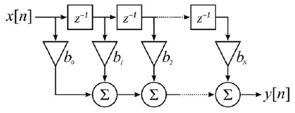 ):
):
 |
Fig. (1) Canonical form of FIR filter. |
The advantage of this architecture is its speed and ability to work in real time. Its disadvantage is the considerable increase of hardware costs.
Implementation of FIR Filters in Frequency Domain
Besides the time-domain implementations, frequency domain implementation is also possible. It is based on the so-called convolution theorem, the essence of which is as follows: the spectrum of the cyclic convolution equals the product of the spectra of the convolved signals (convolution in one domain equals point-wise multiplication in the other domain): S(k) = A(k) * B(k), where A(k) and B(k) are the spectra of the convolved signals, and S(k) is the spectrum of the cyclic convolution of two signals (Fig. 2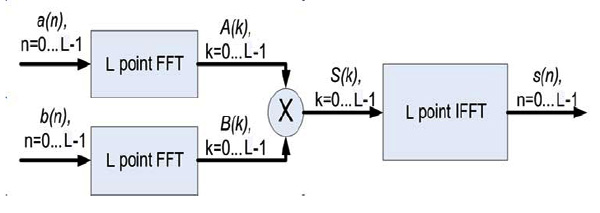 ).
).
 |
Fig. (2) Block diagram of the cyclic convolution calculation in frequency domain. |
Thus, instead of directly implementing the convolution according to the formula, we can convert the signals into frequency domain using fast Fourier transform (FFT), multiply them point-wise, and then do reverse conversion. In this case the result corresponds to the cyclic convolution [4]. Moreover, if we add zeros to the sequences, cyclic convolution calculation becomes equivalent to calculation of the required linear convolution. The advantage of this method is the reduction of operations number, because using FFT schematics we need only n*log2(n) operations, which gives a gain for large values of n.
However, there are some drawbacks. In most cases, the input signal is interpreted as a signal of infinite duration, which is filtered using a limited set of coefficients. Parallel circuit successfully copes with this task in "online" mode, but as regards the methods based on FFT, it is not so easy. Even if we create a converter for conditional infinite number of points, the circuit latency also goes to infinity, because for FFT, to start giving out the resulting values, all needed values should be uploaded beforehand. To solve this problem, various "overlap-add" methods have been developed. They allow to process small size segments and then combine them to get the necessary convolution for the theoretically infinite sequence of points at the output [5].
FIR Filters Implementation via Residue Number System
For further improvement of performance, reliability, accuracy and power consumption, methods based on RNS arithmetic are often used. Using the Chinese remainder theorem, it is possible to decompose the filter structure into a number of parallel independent residue channels, each of which is a FIR filter over a finite field. Such parallelization reduces number of digits of the operands, that improves operating speed and power consumption. Also, adding some redundancy, RNS arithmetic allows increasing device reliability.
Structure of RNS calculators is determined by the set of moduli {m1, m2, …,mN}, that are pairwise coprime. Dynamic range of the RNS is characterized by an interval [0,M), where M = m1 · m2 · ... · mN. Chinese remainder theorem guarantees unique representation of integer numbers from the dynamic range as the set of remainders of the number divided by the moduli from the given set, and also defines the method of restoring the number from its remainders. Thus, the number has the following RNS notation:
where |X|mi is the remainder of the division of X by the modulus mi
Arithmetic operations are performed componentwise Z=X°Y, where X=( x1,x2,...,xr ), Y=( y1,y2,...,yr ), Z=(z1,z2,...,zr), and zi = xi ° yi for i = 1,…,r.. Symbol ° denotes any of the RNS operations: addition, subtraction, or multiplication for corresponding modulus. Thus, the calculations are performed in parallel, independently for each residue channel, that eventually leads to the process acceleration.
One of the main difficulties regarding the practical implementation of RNS-based devices is the problem of effective implementation of forward and reverse converters - devices that convert information from binary to RNS notation and backwards. Building of reverse converters is especially hard because it requires simultaneous addressing all components of RNS notation. For implementing of FIR filters, in this paper we use efficient architectures of forward and reverse converters that were proposed in the previous works [6, 7].
DEVELOPMENT OF RNS-BASED FIR FILTER USING THE CONVOLUTION THEOREM OVER FINITE FIELDS
As it was already stated above, there are many ways of hardware implementation of FIR filters: sequential, parallel, in frequency/time domain, etc. RNS arithmetic provides means for structure parallelization at the level of arithmetic operations, and it can be used for the design of a FIR filter implemented by any method. However, the most promising is the use of RNS-based parallel implementation in frequency domain. There are several prerequisites for this conclusion, the main of which is that for finite fields there is an analogue of the convolution theorem. More precisely, there exists a transform over finite fields similar to Fourier transform, for which convolution theorem over finite fields holds and all symmetric properties are met, that allows using any fast algorithm for computing this transform. The conversion formula is as follows:
Here Ak - is the number-theoretic spectrum of the signal, an is the signal itself, p is the characteristic of the finite field, γ - is the primitive root with index 2t [8]. If the number p is of the form p = q · 2t + 1, then the primitive root with index 2t always exists and equals γ = ɷq.
For a prime modulus m, there is at least one primitive root ɷ ≤ p - 1, such that the set |ɷi|m : i = 0,1,2,...,m - 2 forms all nonzero residues modulo m. The following example shows that ɷ = 3 is a primitive root modulo m = 7:
|30|7 = 1 |33|7 = 6
|31|7 = 3 |34|7 = 4
|32|7 = 2 |35|7 = 5
Exponents of the primitive root by an arbitrary modulo are called "indexes".
Thus, the said conversion is an analog of the discrete Fourier transform for trigonometric basis, where the twiddle factors
Besides the obvious advantages such as of computations paralleling, we achieve better accuracy, since the calculations are carried out in finite fields with integer twiddle factors that eliminates representation errors typical for standard trigonometric method. [4]
The RNS-based FIR filter implementation with the use of number-theoretic fast Fourier transform is presented in the (Fig. 3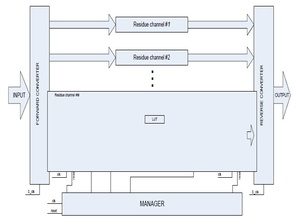 ).
).
 |
Fig. (3) Block schematic diagram of FIR filter in frequency domain. |
The basic structure of the filter consists of forward and reverse converter units, as well as N residue channels of the same type that differ only in characteristic of the finite field over which all arithmetic calculations are carried out. All moduli must have the same binary rank, i.e. they must all be of the form pi = qi · 2t + 1. This fact guarantees that a primitive root γi with index 2t exists in every finite field, that allows to form RNS-based FFT of length 2t. This parameter is the basis of FIR filter as a whole. It also determines the length of input data segments of the infinite sequence to be processed in residue channels and then "glued" in OVERLAP ADDITION block. Moreover, this parameter affects the filter order, and if it equals pi = qi · 2t + 1, the number of filter coefficients must equal 2t-1.
The modular channel consists of a zero padding block, forward FFT block, a unit for multiplication by filter coefficients, inverse FFT block (INV_FFT) and a module for data segments combination. FIR filter behavior in frequency domain implies that the relevant number of zeros are added to input data segments for correct “gluing” of the results in the block for combination of the processed data segments. Taking into consideration the pipelined device architecture, it is necessary to reduce data input frequency in half. In other words, internal FIR frequency Fclk should be two times higher than discretization frequency Fs. For this purpose frequency divider block is added to the schematic (Fig. 4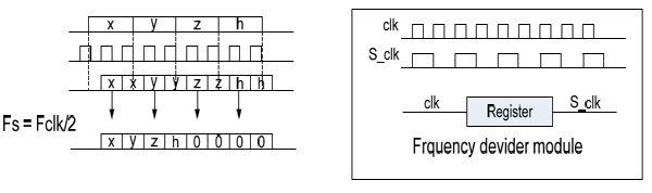 ).
).
 |
Fig. (4) Zero padding block and frequency divider block. |
Overlap addition block combines parts of processed data to make an infinite output sequence of filtered result. Inverse Fourier transform produces blocks of data of length 2t, each of which must be divided into two parts. These two sequences must be combined through pairwise summation. Let’s consider t = 3, and show the overlapping process on (Fig. 5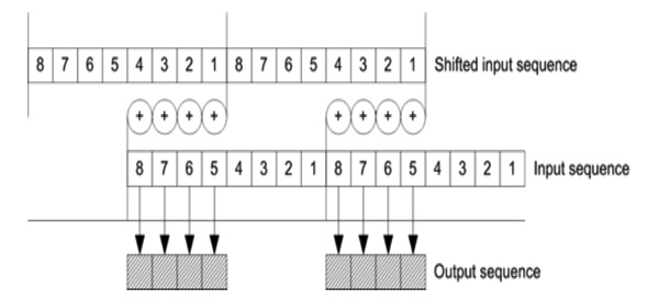 ).
).
 |
Fig. (5) Synthesis results for binary filter in the canonical form. |
|
module overlap_add_41 (dataout, datain, clk, reset, clk_enable); parameter WIDTH=6; input [WIDTH-1:0] datain; input clk, reset, clk_enable; output [WIDTH-1:0] dataout; reg clk_2; wire [WIDTH-1:0] shift1_out, adder_out; // Block Statements always @ (posedge clk or posedge reset) begin if (reset) clk_2 <= 0; else clk_2 <= ~clk_2; end |
Now it is clear that for 2t samples of input data overlap addition block produces 2t-1 output samples. It means that we must use discretization frequency Fs for output data. Verilog code for overlap addition block is given below.
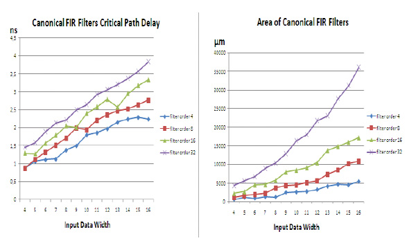 |
Fig. (6) Synthesis results for RNS filter based on convolution theorem over finite field. |
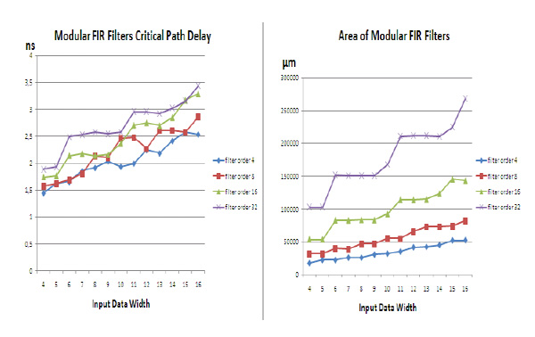 |
Fig. (7) Comparison of RNS and binary schematics for fixed filter orders. |
|
shift_reg_4 #(WIDTH) shift1 (shift1_out, datain, clk, reset, clk_enable); mod_adder #(41, 6) add (adder_out, shift1_out, datain); slow_down_4 #(WIDTH) slow (dataout, adder_ out, clk, clk_2, reset, clk_enable); endmodule |
All internal blocks including Fourier transform block (FFT) are maximally pipelined to achieve the smallest clock frequency. Control unit MANAGER provides for the synchronization of device parts and device as a whole. It is also responsible for supplying the address of the cell holding the filter coefficient to the memory connected to the multiplier.
SYNTHESIS RESULTS
The result of the design is the IP core implementing RTL circuit description in Verilog HDL. All IP cores, developed during related work are available on the author’s web site [9]. IP core parameters are the filter coefficients and the input data digit capacity. To evaluate the efficiency of the proposed approach, experiment was carried out on the synthesis of RNS-based FIR filters using Synopsys CAD tools and Nangate 45 nm Open Cell Library. The order of the filter was chosen in the range of 4 to 32 points. Number of bits is in the range of 4 - 16. Critical path delay and circuit area were evaluated. Also, for the same set of parameters FIR filter in canonical form was designed. Results are presented in Figs. (6 , 7
, 7 ) and Table 1.

CONCLUSION
The synthesis results show that the proposed schematic outperforms the traditional variant with regard to clock frequency for large-scale input data and higher filter order, however, it requires sufficiently greater area. And if at first glance, the results may seem disappointing – actually it is not so. RNS-based filters have some advantages which are not reflected in the presented diagrams. First, the filtered output signal of the RNS block based on the FFT over a finite field is much more accurate than the output signal of the conventional binary filter. This is due to the fact that for FFT over a finite field twiddle coefficients are the elements of this finite field, i.e. integer numbers. Thus, we avoid errors in the representation of the coefficients. Another advantage of the proposed approach is the fact that by adding extra modular channels we are able to control and even correct errors that arise during the computation. Future developments will be directed to the implementation of sequential RNS filters based on FFT over a finite field.
CONFLICT OF INTEREST
The authors confirm that this article content has no conflict of interest.
ACKNOWLEDGEMENTS
Declared none.