- Home
- About Journals
-
Information for Authors/ReviewersEditorial Policies
Publication Fee
Publication Cycle - Process Flowchart
Online Manuscript Submission and Tracking System
Publishing Ethics and Rectitude
Authorship
Author Benefits
Reviewer Guidelines
Guest Editor Guidelines
Peer Review Workflow
Quick Track Option
Copyediting Services
Bentham Open Membership
Bentham Open Advisory Board
Archiving Policies
Fabricating and Stating False Information
Post Publication Discussions and Corrections
Editorial Management
Advertise With Us
Funding Agencies
Rate List
Kudos
General FAQs
Special Fee Waivers and Discounts
- Contact
- Help
- About Us
- Search


The Open Mechanical Engineering Journal
(Discontinued)
ISSN: 1874-155X ― Volume 14, 2020
Identification of the Mechanical Properties of Tires for Wheelchair Simulation
Alberto Doria1, *, Luca Taraborrelli1, Tarek Jomaa1, Tom Peijs2, Mario Potter2, Sunjoo Advani2, Larry Crichlow3
Abstract
The development of high performance wheelchairs and wheelchair simulators requires dynamic models taking into account the properties of tires. In this paper the properties of two wheelchair tires are measured by means of a rotating disc testing machine and are compared with the properties of bicycle tires, which have similar dimensions and structure. Tests are carried out considering variations in speed, inflation pressure and load. The possibility of fitting experimental results with the Magic Formula, the Dugoff formula and a linear model is discussed. A dynamic model of a wheelchair is developed, which includes a linear tire model derived from experimental results. Steady turning and slalom manoeuvres are simulated. Numerical results show the effect of tire properties on the handling characteristics of the wheelchair.
Article Information

Identifiers and Pagination:
Year: 2016Volume: 10
First Page: 183
Last Page: 200
Publisher Id: TOMEJ-10-183
DOI: 10.2174/1874155X01610010183
Article History:
Received Date: 22/07/2016Revision Received Date: 24/10/2016
Acceptance Date: 01/11/2016
Collection year: 30/12/2016
Collection year: 2016
open-access license: This is an open access article licensed under the terms of the Creative Commons Attribution-Non-Commercial 4.0 International Public License (CC BY-NC 4.0) (https://creativecommons.org/licenses/by-nc/4.0/legalcode), which permits unrestricted, non-commercial use, distribution and reproduction in any medium, provided the work is properly cited.
* Address correspondence to this author at the Department of Industrial Engineering, University of Padova, Via Venezia 1, 35131, Padova, Italy; Tel: +39 0498276803; Fax: +39 049 8277599; E-mail: alberto.doria@unipd.it.
| Open Peer Review Details | |||
|---|---|---|---|
| Manuscript submitted on 22-07-2016 |
Original Manuscript | Identification of the Mechanical Properties of Tires for Wheelchair Simulation | |
1. INTRODUCTION
Independence and mobility are very important aspects of modern day life. There are an estimated 650 million to one billion elderly people and people with injuries and/or disabilities [1R.B. Zoellick, and M. Chan, World Report on Disability. Tech. Report, World Health Organization, World Bank, 2011] worldwide of which around 10% require a wheelchair (manual or other kinds) [2"Guidelines on the provision of Manual Wheelchairs in less resourced settings", In: Disability & Rehabilitation, WHO, 2008.]. For these people a good wheelchair is essential to maintain their independence and mobility with safety, comfort and dignity.
In order to help solve the challenges faced by manual wheelchair users and their caregivers, research using a high fidelity manual wheelchair simulator could prove to be very useful.
A wheelchair simulator would allow researchers also to perform research and training in a safe and controllable environment. To this end, an advanced manual wheelchair simulator is being developed by Toronto Rehabilitation Institute (TRI) [3L.R. Crichlow, "Development of a Comprehensive Mathematical Model and Physical Interface for Manual Wheelchair Simulation", Master’s thesis, University of Toronto, Toronto, Canada, 2011] in Toronto, Canada, and will become part of the Challenging Environment Assessment Laboratory or CEAL [4S. Advani, M. Potter, and G. Fernie, "CEAL - flight simulation technology applied to rehabilitation research", In: In: AIAA Modeling and Simulation Technologies Conference, Toronto, Ontario, Canada, 2000.], located at the Toronto Rehabilitation Institute.
The Toronto Rehabilitation Institute has designed a wheelchair simulator which can be used in the virtual environment of StreetLab (see Fig. 1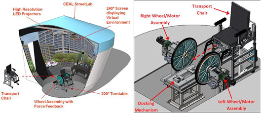 ). An initial wheelchair model has been developed [3L.R. Crichlow, "Development of a Comprehensive Mathematical Model and Physical Interface for Manual Wheelchair Simulation", Master’s thesis, University of Toronto, Toronto, Canada, 2011]. Under the supervision of International Development of Technology B.V., Breda, The Netherlands (IDT B.V.), a study to further enhance the tire model has been performed to see if this would lead to improvements of the wheelchair simulation performance and fidelity. To enhance the tire model, a good knowledge of actual tire properties is needed.
 |
Fig. (1) Design of the wheelchair simulator using the StreetLab virtual environment. |
Very few scientific papers discussing the properties of wheelchair tires have been presented in the past [3L.R. Crichlow, "Development of a Comprehensive Mathematical Model and Physical Interface for Manual Wheelchair Simulation", Master’s thesis, University of Toronto, Toronto, Canada, 2011, 6A.M. Kwarciak, M. Yarossi, A. Ramanujam, T.A. Dyson-Hudson, and S.A. Sisto, "Evaluation of wheelchair tire rolling resistance using dynamometer-based coast-down tests", J. Rehabil. Res. Dev., vol. 46, no. 7, pp. 931-938, 2009.
[http://dx.doi.org/10.1682/JRRD.2008.10.0137] [PMID: 20104415] -9D. H. Veeger, and L. H. van der Woude, "The effect of rear wheel camber in manual wheelchair Propulsion", J. Rehab. Res. Develop, vol. 26, no. 2, pp. 37-46, 1989.], most of them focusing only on rolling resistance.
A study has been performed by Padova University and IDT to enhance the characterization of wheelchair tires.
The first phase of the research focused on the measurement of tire properties by means of the tire testing machine of Padova University, which has been used in the past for identifying the mechanical properties of motorcycle and scooter tires [10V. Cossalter, A. Doria, R. Lot, N. Ruffo, and M. Salvador, "Dynamic properties of motorcycle and scooter tires: measurement and comparison", Veh. Syst. Dyn., vol. 39, no. 5, pp. 329-352, 2003.
[http://dx.doi.org/10.1076/vesd.39.5.329.14145] , 11V. Cossalter, A.E. Doria, A. Doria, L. Taraborrelli, and M. Massaro, "Identification of the characteristics of motorcycle and scooter tyres in the presence of large variations in inflation pressure", Veh. Syst. Dyn., vol. 52, no. 10, pp. 1333-1354, 2014.
[http://dx.doi.org/10.1080/00423114.2014.940981] ] as well as bicycle tires in a more recent study [12A. Doria, M. Tognazzo, G. Cusimano, V. Bulsink, A. Cooke, and B. Koopman, "Identification of the mechanical properties of bicycle tyres for modelling of bicycle dynamics", Veh. Syst. Dyn., vol. 51, pp. 405-420, 2012.
[http://dx.doi.org/10.1080/00423114.2012.754048] ]. The behavior of wheelchair tires under different working conditions has been investigated. Subsequently, the curves of measured tire forces and torques have been fitted by means of linear and non-linear functions (MF model and Dugoff model), the capabilities and limits of the various models have been analyzed and discussed. Finally, a numerical model of a wheelchair equipped with a linear tire model derived from experimental results has been developed. Results show that variations in the cornering stiffness, self-aligning stiffness, and camber stiffness cause variations in the handling performance of the wheelchair.
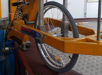 |
Fig. (2) The wheelchair tire on the testing machine. |
2. EXPERIMENTAL EQUIPMENT AND METHODS
Wheelchair tires were tested on the tire testing machine of Padova University [10V. Cossalter, A. Doria, R. Lot, N. Ruffo, and M. Salvador, "Dynamic properties of motorcycle and scooter tires: measurement and comparison", Veh. Syst. Dyn., vol. 39, no. 5, pp. 329-352, 2003.
[http://dx.doi.org/10.1076/vesd.39.5.329.14145] ], which is shown in Fig. (2 ). This test rig was originally developed for the purpose of testing motorcycle and scooter tires. The wheel is mounted on a hinged arm that creates the side slip angle (±9°) and\or the camber angle (±50°). The wheel rolls freely on a rotating disc (diameter 3m) covered by a high friction material (Safety Walk grit 60 manufactured by 3M Company) to simulate the road. Data are collected by means of three load cells mounted on the arm. The first load cell is mounted in the lateral direction, locks the hinged arm and measures the lateral force. The two other load cells measure the moment around the diametrical axis that passes through the contact patch and the moment about the wheel spin axis respectively. The load cells are then connected to the computer through a data acquisition system composed of some specific modules (NI-9237 and NI-CDAQ 9188) to convert the signals.
Side slip tests are performed by varying the side slip angle while fixing the camber angle at zero (see Fig. 3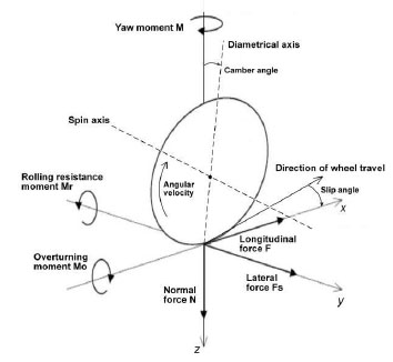 ) for the definition of angles). The resulting curves are the side slip force and self-aligning torque.
 |
Fig. (3) The coordinate system for the definition of tire forces and torques. |
The self-aligning torque results from the non-symmetric distribution of stresses along the contact patch and it tends to align the wheel to the direction of speed if a perturbation takes place [13V. Cossalter, Motorcycle Dynamics, 2nd ed. Raleigh, NC: Lulu.com, 2007., 14H. B. Pacejka, Tire and Vehicle Dynamics, Butterworth-Heinemann: Oxford, 2005.].
Camber tests are performed by varying the camber angle while fixing the side slip angle at zero. The resulting curves are the camber force and the twisting torque. The twisting torque represents the tendency of the cambered wheel to move along a trajectory with a curvature radius smaller than the one demanded by the steady turning manoeuver; it does not tend to align the wheel [13V. Cossalter, Motorcycle Dynamics, 2nd ed. Raleigh, NC: Lulu.com, 2007.].
The tests are carried out in steady-state condition, which is achieved by keeping the hinged arm firm for a specified interval of time (5s by default) for each assigned value of side slip (or camber) angle. During this interval, measurements are made and the mean value of measurements carried out for each slip (or camber) angle is calculated by the elaboration software.
The first load cell (responsible for lateral force measurement) measures the actual lateral force with an additional force generated by the curvature of the track that distorts the contact patch of the tire. For convenience, this additional lateral force is called the curvature force.
The curvature force, which depends on the position of the contact point on the disc and is always directed towards the disc outside, is cancelled by carrying out measurements for positive and negative values of side slip (or camber) angle. The resulting measurements have the same curvature force and side slip (or camber) forces with the same modulus but opposite signs. The elaboration software calculates the half difference between forces corresponding to the positive and negative values of side slip (or camber) angle. This is a good estimate of the actual side slip (or camber) force, because the curvature forces cancel each other. The side slip (or camber) force at zero side slip (or camber) angle is simply set to zero, since the measured value results only from the curvature force.
To perform the correction, measured data is processed by means of a MATLAB code that generates the curves for side slip force, camber force, self-aligning and twisting torque.
The tire testing machine has good repeatability, detailed information about repeatability and accuracy can be found in [10V. Cossalter, A. Doria, R. Lot, N. Ruffo, and M. Salvador, "Dynamic properties of motorcycle and scooter tires: measurement and comparison", Veh. Syst. Dyn., vol. 39, no. 5, pp. 329-352, 2003.
[http://dx.doi.org/10.1076/vesd.39.5.329.14145] , 12A. Doria, M. Tognazzo, G. Cusimano, V. Bulsink, A. Cooke, and B. Koopman, "Identification of the mechanical properties of bicycle tyres for modelling of bicycle dynamics", Veh. Syst. Dyn., vol. 51, pp. 405-420, 2012.
[http://dx.doi.org/10.1080/00423114.2012.754048] ].
Since wheelchair tires are characterized by vertical loads smaller than the ones of motorcycle tires, a counterweight is installed to reduce the vertical load (N) and the tests are carried out under two conditions N = 400 N and N = 600 N, which are compatible with wheelchair tires.
3. EXPERIMENTAL RESULTS
In the framework of this research two typical wheelchair tires produced by different manufacturers were tested. In the following they are named tire A and tire B respectively. The size of both tires is 24 x 1.3/8 inches (37-500 ETRTO) and maximum inflation pressure is 5 bar. Tire A is a high quality tire made by a well-known manufacturer, tire B is a low cost tire.
First both tires were tested in a reference condition with vertical load 400 N, inflation pressure 4 bar and disc speed 4 km/h. Side slip angle (λ) ranged from 0° to 5°, this range includes both normal operations (λ < 1°) and rough manoeuvers with large side slip. Camber angle (φ) ranged from 0° to 10° to include a wide set of possible fittings of the wheels on the chair.
Results of these tests are represented in Fig. (4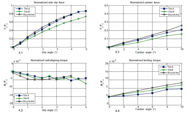 ) in terms of normalized forces and torques: a normalized force is a measured force divided by the vertical load, whereas a normalized torque is a measured torque divided by the vertical load. The curves of wheelchair tires are compared with the ones of a high performance bicycle tire (size 37-622 ETRTO) tested at the same value of inflation pressure, vertical load and speed.
 |
Fig. (4) Forces and torques of wheelchair and bicycle tires in reference conditions (vertical load 400 N, inflation pressure 4 bar and disc speed 4 km/h). |
The curves of normalized side slip force (Fig. 4.1) show that this component of lateral force increases in monotonic way with side slip angle. In the side slip range here considered no saturation phenomenon takes place; it is worth highlighting that also in car tires saturation takes place for higher values of side slip angle [14]. Tire A for every value of side slip generates larger forces than tire B. The curve of tire A is very close to the one of the high performance bicycle tire. The slope of the curves of Fig. (4.1) near the origin is named normalized cornering stiffness. Cornering stiffness is the product of normalized cornering stiffness and vertical load.
The curves of normalized self-aligning torque are represented in Fig. (4.2). The curves of the two tires are rather close and both show a tendency to saturation above 3°. The maximum values (in modulus) of self-aligning torques of tire A and B are similar to the maximum value (in modulus) of the self-aligning torque of the bicycle tire, but the bicycle tire shows a steeper slope near the origin and reaches saturation for a lower value of side slip angle. The slope of the curves of normalized self-aligning torque near the origin is named normalized self-aligning stiffness.
The curves of normalized camber force (Fig. 4.3) are regular and monotonic for both tires, but tire A exhibits larger values than tire B and its curve is rather close to the one of the high performance bicycle tire. The slope of the curves of normalized camber force near the origin is named normalized camber stiffness. Finally, the curves of twisting torque against camber angle (Fig. 4.4) are almost linear, in this case the curve of tire B is closer to the one of the bicycle tire.
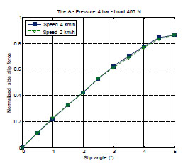 |
Fig. (5) Effect of forward speed on side slip force. |
The high quality of tire A is confirmed by the large forces that it generates, which are similar to the ones generated by the bicycle tire.
Then the effect of working conditions was analyzed carrying out specific tests in which only one parameter was varied at a time.
In the context of rehabilitation research, wheelchair simulations will be performed at relatively low speeds between 0 and 4 km/h. Experimental tests showed that variations in the speed of the testing machine have a negligible effect on the measured tire properties. To give an example, Fig. (5 ) shows the effect of a decrease in speed on the side slip force generated by tire A, the difference between the two curves is negligible. It is worth remembering that disc speed corresponds to wheelchair speed.
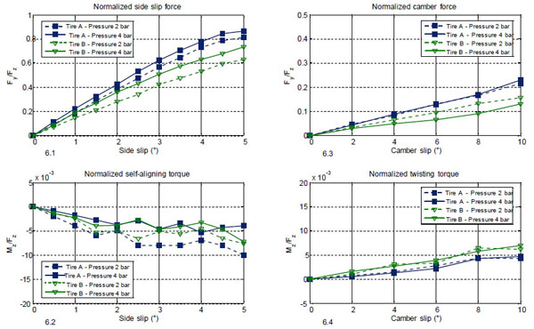 |
Fig. (6) Effect of inflation pressure on tire forces and torques. |
Fig. (6 ) deals with the effect of inflation pressure on tire performance, a strong decrease in tire pressure (from 4 to 2 bar) is considered.
Tire properties related to side slip angle are strongly affected by inflation pressure. In both tires a decrease in inflation pressure causes a large decrease in the side slip force generated at the same side slip angle, see Fig. (6.1). This trend agrees with the ones measured in bicycle tires [12A. Doria, M. Tognazzo, G. Cusimano, V. Bulsink, A. Cooke, and B. Koopman, "Identification of the mechanical properties of bicycle tyres for modelling of bicycle dynamics", Veh. Syst. Dyn., vol. 51, pp. 405-420, 2012.
[http://dx.doi.org/10.1080/00423114.2012.754048] ] and the ones measured in motorcycle and scooter tires, which sometimes also show a saturation at high pressure [11V. Cossalter, A.E. Doria, A. Doria, L. Taraborrelli, and M. Massaro, "Identification of the characteristics of motorcycle and scooter tyres in the presence of large variations in inflation pressure", Veh. Syst. Dyn., vol. 52, no. 10, pp. 1333-1354, 2014.
[http://dx.doi.org/10.1080/00423114.2014.940981] ]. Self aligning torque (Fig. 6.2) increases (in modulus) when inflation pressure decreases, probably because the contact patch becomes larger. This result is in agreement with the ones obtained measuring bicycle and motorcycle tires [11V. Cossalter, A.E. Doria, A. Doria, L. Taraborrelli, and M. Massaro, "Identification of the characteristics of motorcycle and scooter tyres in the presence of large variations in inflation pressure", Veh. Syst. Dyn., vol. 52, no. 10, pp. 1333-1354, 2014.
[http://dx.doi.org/10.1080/00423114.2014.940981] , 12A. Doria, M. Tognazzo, G. Cusimano, V. Bulsink, A. Cooke, and B. Koopman, "Identification of the mechanical properties of bicycle tyres for modelling of bicycle dynamics", Veh. Syst. Dyn., vol. 51, pp. 405-420, 2012.
[http://dx.doi.org/10.1080/00423114.2012.754048] ]. Coming to camber force, Fig. (6.3) shows that camber force generated by tire A is not influenced by inflation pressure, like in bicycle tires [12A. Doria, M. Tognazzo, G. Cusimano, V. Bulsink, A. Cooke, and B. Koopman, "Identification of the mechanical properties of bicycle tyres for modelling of bicycle dynamics", Veh. Syst. Dyn., vol. 51, pp. 405-420, 2012.
[http://dx.doi.org/10.1080/00423114.2012.754048] ]; whereas camber force generated by tire B tends to increase if inflation pressure decreases, like in many motorcycle tires [11V. Cossalter, A.E. Doria, A. Doria, L. Taraborrelli, and M. Massaro, "Identification of the characteristics of motorcycle and scooter tyres in the presence of large variations in inflation pressure", Veh. Syst. Dyn., vol. 52, no. 10, pp. 1333-1354, 2014.
[http://dx.doi.org/10.1080/00423114.2014.940981] ].
Like in bicycle tires [12A. Doria, M. Tognazzo, G. Cusimano, V. Bulsink, A. Cooke, and B. Koopman, "Identification of the mechanical properties of bicycle tyres for modelling of bicycle dynamics", Veh. Syst. Dyn., vol. 51, pp. 405-420, 2012.
[http://dx.doi.org/10.1080/00423114.2012.754048] ] inflation pressure has a negligible effect on twisting torque, see Fig. (6.4).
The last parameter here considered is vertical load, its effect is shown in Fig. (7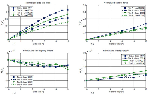 ). In wheelchair tires, like in bicycle [12A. Doria, M. Tognazzo, G. Cusimano, V. Bulsink, A. Cooke, and B. Koopman, "Identification of the mechanical properties of bicycle tyres for modelling of bicycle dynamics", Veh. Syst. Dyn., vol. 51, pp. 405-420, 2012.
[http://dx.doi.org/10.1080/00423114.2012.754048] ] and motorcycle tires [11V. Cossalter, A.E. Doria, A. Doria, L. Taraborrelli, and M. Massaro, "Identification of the characteristics of motorcycle and scooter tyres in the presence of large variations in inflation pressure", Veh. Syst. Dyn., vol. 52, no. 10, pp. 1333-1354, 2014.
[http://dx.doi.org/10.1080/00423114.2014.940981] ], when vertical load increases lateral forces do not increase proportionally, because normalized lateral forces decrease when vertical load increases. This effect is particularly important for side slip force (Fig. 7.1). The effect of vertical load in tire torques is less prominent: in tire A self aligning and twisting torques are almost unaffected by tire load, whereas in tire B both torque components decrease slightly (in modulus) when load increases.
 |
Fig. (7) Effect of vertical load on tire forces and torques. |
4. FITTING OF MEASURED DATA
Measured tire forces and torques were fitted with the Pacejka “Magic Formula” (MF) tire model, the Dugoff tire model [15H. B. Pacejka, Tire and Vehicle Dynamics, Butterworth-Heinemann: Oxford, 2005.] and a simple linear model.
The Magic Formula [14] represents steady-state tire characteristics very accurately and is applied throughout the automotive and motorcycle tire industry. Its basic form is:
| Y = D sin[C arctan(Bx − E(Bx − arctan Bx))] | (1) |
In which variable Y may represent a force or moment component, variable x may represent side-slip or camber angle and B, C, D and E are coefficients. The four coefficients are calculated by means of a best fitting method.
In the steady-state Dugoff tire model the side slip force Fs and self-aligning torque M are represented by equations 2 and 3.
| Fs = Cλ tan(λ) f (γ) | (2) |
| M = −Cλ tan(λ) f (γ)cp | (3) |
With
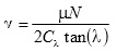 |
(4) |
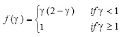 |
(5) |
In which Cλ is cornering stiffness, cp tire trail [15H. B. Pacejka, Tire and Vehicle Dynamics, Butterworth-Heinemann: Oxford, 2005., 16R. Rajamani, Vehicle Dynamics and Control., 2nd ed. Springer US: New York, 2011.], μ friction coefficient and N vertical load.
The Dugoff tire model is simpler and less accurate than the MF model, but it is easy to implement and requires only few coefficients for studying lateral tire behaviour: cornering stiffness, friction coefficient and pneumatic trail. Currently the Dugoff model is used in the TRI wheelchair simulator.
Figs. (8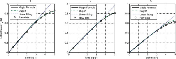 and 9
and 9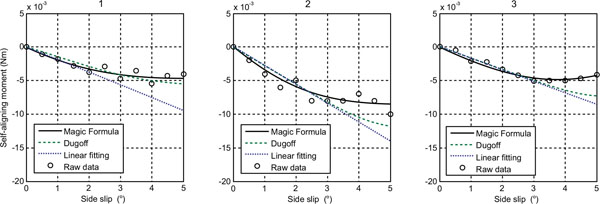 ) show the fittings of measured data by means of the MF and the Dugoff model. Tire A (high quality tire) is considered in three conditions: reference condition (pressure 4 bar, load 400 N and speed 4 m/s); decreased inflation pressure (2 bar), increased load (600 N).
 |
Fig. (8) Fittings of lateral force raw data by means of the Magic Formula and Dugoff models for tire A; (1) reference condition, (2) decreased inflation pressure, (3) increased load. |
 |
Fig. (9) Fittings of self-aligning moment raw data by means of the Magic Formula and Dugoff models for tire A; (1) reference condition, (2) decreased inflation pressure, (3) increased load. |
The MF tire model is able to fit well both side slip force and self-aligning moment in the various conditions. The Dugoff tire model fits well side slip force in the whole range of side slip angles in the various conditions and fits rather well self- aligning torque in reference conditions. When inflation pressure decreases or vertical load increases and, consequently, the contact patch enlarges, the Dugoff tire model shows some limits in the fitting of self-aligning torque for large values of side slip angle (λ>3°) where tire behaviour is not linear.
It is worth highlighting that for small side slip angles (<3°) both models tend to give a linear fitting of lateral force and self-aligning moment. Therefore a linear tire model based on the slope near the origin is enough to simulate manoeuvres with small side slip angles.
Standard wheelchairs are manufactured without intentional camber, but tolerances may result in some camber. In this case the trends of Figs. (4, 6 and 7) clearly highlight that a linear model is enough to represent camber force and twisting torque for small camber angles (<6°).
5. MATHEMATICAL MODEL
In this section the model of a wheelchair moving on a flat road is developed with the aim of studying the effect of the measured tire properties on typical maneuvers. The model, which is an evolution of the one presented in [17S. Song, M. Chi Kam Chun, J. Huissoon, and S.L. Waslander, "Pneumatic trail based slip angle observer with dugoff tire model", IEEE Intelligent Vehicles Symposium (IV), Dearborn, Michigan, USA, 2014
[http://dx.doi.org/10.1109/IVS.2014.6856538] ], includes five rigid bodies: the wheelchair with the user, the rear wheels and the front castering wheels (see Fig. 10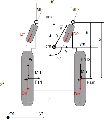 ).
).
 |
Fig. (10) Wheelchair model. |
The main assumptions that are made to develop the model are here summarized:
- The user is a rigid body firmly attached to the chair and exerts two propulsive torques on the rear wheels.
- The wheels roll without slipping in the longitudinal direction, which is the intersection between the wheel plane and the road plane.
- The wheels can slip in the lateral direction, which is the direction in the road plane perpendicular to the wheel plane.
- The side slip angles are small, therefore their trigonometric functions can be linearized, tire forces and torques can be approximated as linear functions of side slip angle. This assumption is currently made for studying standard manoeuvers of four wheeled vehicles [18B. Johnson, and J. Aylor, "Dynamic modeling of an electric wheelchair", IEEE Transact. Indust. Appl., vol. 2, no. 5, pp. 1284-1293, 1985.
[http://dx.doi.org/10.1109/TIA.1985.349556] ]. - The camber angles are small, therefore their trigonometric functions can be linearized.
- The load transfer between front and rear wheels is neglected, because neither sudden accelerations nor sudden deceleration are compatible with standard operations of wheelchairs.
- The lateral load transfer (between right and left wheels) is neglected, because large centrifugal forces are not compatible with standard operations of wheelchairs.
- The mass and the moment of inertia of the small castering wheels are neglected.
- Transient tire properties (e.g. relaxations length) are neglected because they have a very small effect on cornering properties at low speed. Typically they do affect stability of motorcycles at high speed [13V. Cossalter, Motorcycle Dynamics, 2nd ed. Raleigh, NC: Lulu.com, 2007.].
The degrees of freedom of the system are five: longitudinal and lateral displacements of the center of mass of the chair-user, rotation ψ of the chair-user in the plane of motion, caster angles of front wheels (δfr and δfl).
Equations of motion are written in coordinate system xm ym, which moves with the
vehicle. Absolute velocity of the center of mass of the system (V̅) has components u and v along axes xm ym respectively. First the dynamic equilibrium of the right caster wheel represented in Fig. (11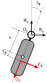 ) is considered. Newton’s second law gives:
 |
Fig. (11) Caster wheel model. |
| mf ax = −Dfr cos (δ fr) − Fsfr sin (δ fr) + Rx | (6) |
| mf ay = −Dfr sin (δ fr) + Fsfr cos (δ fr) + Ry | (7) |
in which mf is caster wheel mass, δfr caster angle, Fsfr lateral force, Dfr rolling resistance, which depends on the total weight of the system; ax and ay are the components of absolute acceleration of wheel center of mass in reference system xm ym zm and Rx, Ry are the components of reaction forces generated by the chair on the wheel (in reference system xm ym zm).
Since mf is very small with respect to total mass, inertia forces in equations (6) and (7) can be neglected [17S. Song, M. Chi Kam Chun, J. Huissoon, and S.L. Waslander, "Pneumatic trail based slip angle observer with dugoff tire model", IEEE Intelligent Vehicles Symposium (IV), Dearborn, Michigan, USA, 2014
[http://dx.doi.org/10.1109/IVS.2014.6856538] ].
Angular momentum equation about pivot point Or of the right wheel is:
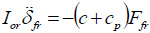 |
(8) |
in which Ior is the moment of inertia of the wheel about the pivot point, c is trail and coincides with the distance between Or and the center of mass of the wheel. cp is pneumatic trail, which is due to the non-symmetric distribution of lateral tire force and generates the self-aligning torque [14]. Rolling resistance Dfr does not generate a moment about Or. Similar equations hold true for the left wheel.
Equation (8) shows that in steady state condition (δfr constant) the lateral force is zero. Since Ior is very small, equation (8) shows that also in transient condition a very small lateral force is required, for this reason the side slip angle of caster wheels can be neglected. In this condition equations (6) and (7) show that reaction forces Rx and Ry depend only on rolling resistance [19T. Gillespie, Fundamentals of Vehicle Dynamics, SAE International: Warrendale PA, 1992.].
Now the dynamic equilibrium of the whole system is considered.
The attitude angles of the front and rear wheels can be calculated analyzing the rigid body motion of the whole system in plane xm ym. Attitude angle (β) of a wheel is the angle from axis xm to the velocity of the wheel hub, which is due to rigid body motion of the vehicle. In the present case, since the front wheels can rotate freely about their pivots, the front attitude angles are equal to the caster angles. In rear wheels attitude angles are equal and opposite in sign to side slip angles (which are the angles from the velocity of wheel hub to the symmetry plane of the wheel. Therefore the following equations hold):
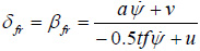 |
(9) |
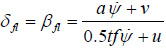 |
(10) |
 |
(11) |
 |
(12) |
In which tf is front tread, tr rear tread, a distance from center of mass (CM) to front wheel pivots, b distance from CM to rear wheel axles. Index fr means front right, fl front left, rr rear right and rl rear left.
Lateral forces on the rear wheels Fssr Fsrl can be expressed as functions of calculated side slip angles and of camber angles (φr φl) by means of the cornering stiffness (Cλ) and camber stiffness (Cφ) identified from experimental tests (linear approximation). It is worth highlighting that in normal operations of wheelchairs camber angles are caused by small assembly errors.
| Fsrr = Cλr λrr + Cφrφr | (13) |
| Fsrl = Cλr λrl + Cφrφl | (14) |
In section 3 tire torques were measured. They are included in the model considering simple linear relations between torques (Mrr Mrl) and angles, which are true for small side slip and camber angles.
| M rr = −Cmλr λrr + Cmφrφr | (15) |
| M rl = −Cmλr λrl + Cmφrφl | (16) |
In which Cmλ and Cmφ are self-aligning and twist stiffness respectively. Rolling resistance forces (D) oppose to forward motion (see Fig. 11) depend on rolling resistance coefficients (ff fr) and vertical loads [5J.J. Chua, F.K. Fuss, and A. Subic, "Non-linear rolling friction of a tyre- caster system, analysis of a rugby wheelchair", Proc. IMechE Part D, vol. 225, pp. 1015-1020, 2010.
[http://dx.doi.org/10.1243/09544062JMES2485] , 20F. Chénier, P. Bigras, and R. Aissaoui, "A new dynamic model of the manual wheelchair for straight and curvilinear propulsion", In: In:
IEEE International Conference on Rehabilitation Robotics, Rehab Week Zurich, 2011.
[http://dx.doi.org/10.1109/ICORR.2011.5975357] ] on front and rear wheels (Nf Nr), which are calculated from static equilibrium assuming the vehicle symmetric with respect to plane xm zm.
 |
(17) |
 |
(18) |
 |
(19) |
In which m is total mass and g is acceleration due to gravity.
Once calculated tire forces, Newton’s second law gives:
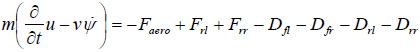 |
(20) |
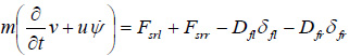 |
(21) |
in which Faero is a resistance force due to the interaction with air, which is negligible at low speed. Frl Frr are the left and right traction forces at the contact patch exerted by the user on the rear wheels. Angular momentum equation about
the CM of the system is:
 |
(22) |
In which Iz is the moment of inertia of the whole system about the vertical axis intersecting the CM. Equations (20) (21) and (22) are a system of first order linear differential equations. If forward speed u is assigned and constant, equation (20) becomes an algebraic equation and equations (21) and (22) can be solved independently from (20) to calculate v (lateral velocity) and ψ˙ (yaw angular velocity). In the framework of this research the system of differential equations has been solved numerically by means of a MATLAB 2014 code.
It is worth highlighting that to solve (21) and (22) only the difference between left and right traction force is needed. Actually this difference determines the directional behavior of the vehicle. Finally, from equation (20) it is possible to calculate the global propulsive force (Frl+Frr), which is needed to move the vehicle withstanding friction and aerodynamic forces. Once v and ψ˙ are calculated it is possible to calculate the radius of curvature (Rc) of the trajectory of the CM:
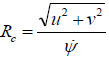 |
(23) |
6. NUMERICAL RESULTS
In this section two reference maneuvers are considered: steady turning and slalom. Steady turning gives useful information about the behavior of the wheelchair in a curve, which can be considered as a part of the steady turning trajectory. Slalom is representative of actual maneuvers performed by the user to avoid obstacles. To generate a steady turning maneuver the user exerts on the two rear wheels two forces that have a constant difference 2ΔF that generates a constant torque (tr ΔF) about the vertical axis. To perform a slalom maneuver the user exerts on the rear wheels two forces whose difference varies with harmonic law: 2ΔF = 2ΔFo cos(2πt / T ), in which ΔF0 is constant and T is the period of the maneuver.
First the effect of tire properties related to side slip is dealt with, because section 3 has shown that they can change significantly if the tires are changed or operating conditions (load, inflation pressure) vary. Finally the effect of camber angle, which can change owing to a different set up of the wheel on the chair, is considered.
6.1. Effect of Cornering Stiffness
Three values of cornering stiffness were considered: the reference value of tire A obtained from experimental tests at 4 bar, 400 N and 4 km/h (see Table 1); a low value, which is half the reference value; an high value, which is twice the reference value.
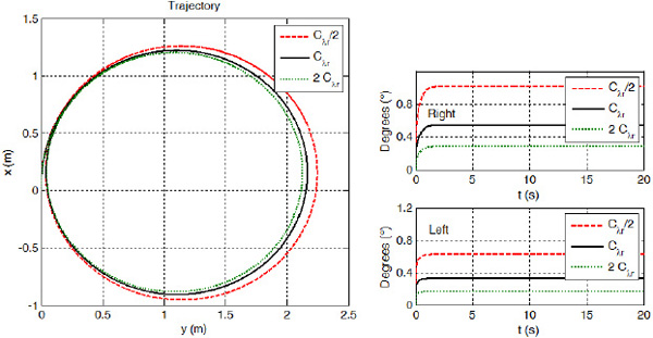 |
Fig. (12) Effect of cornering stiffness on steady turning trajectory of CM and side slip angles. |
Fig. (12 ) shows the effect of cornering stiffness on the trajectory in the steady- turning maneuver with a forward speed of 3.6 km/h. From a closer look of the graph, it is worth noticing that the radius of the trajectory of the CM slightly decreases if the cornering stiffness increases. This result agrees with the effect of the cornering stiffness on the values of slip angle for the right and left rear wheels, which are shown in the same figure. It is possible to notice that the slip angles exhibit roughly an inversely proportional behavior with respect to the value of cornering stiffness. The values of the slip angles are lower than 1° in most cases, this result confirms the correctness of the linearization of the trigonometric functions of the model.
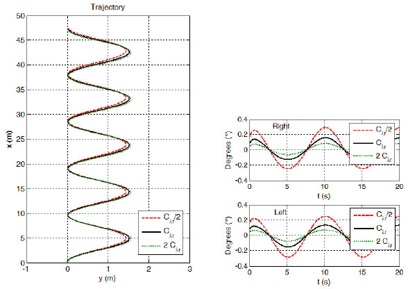 |
Fig. (13) Effect of cornering stiffness on slalom trajectory of CM and side slip angles. |
Fig. (13 ) shows the effect of cornering stiffness on the trajectory in the slalom maneuver. For this maneuver, the effect of the cornering stiffness on the trajectory is rather limited, and an increase in the stiffness causes a small increase in the amplitude of the trajectory. It is interesting to highlight that the trajectory with larger amplitude shows a lag with respect to the trajectory with smaller amplitude. Form a physical point of view, since the forward speed of the vehicle u is constant, if the trajectory becomes larger more time is spent in order to carry out the lateral displacement and the vehicle moves less in the longitudinal direction. The curves of the side slip angles of the right and left rear wheels show that if the cornering stiffness increases, the amplitudes decrease. The curves are also asymmetrical with respect to the axis of abscissas: the right wheel shows a positive mean value, the left wheel shows a negative mean value.
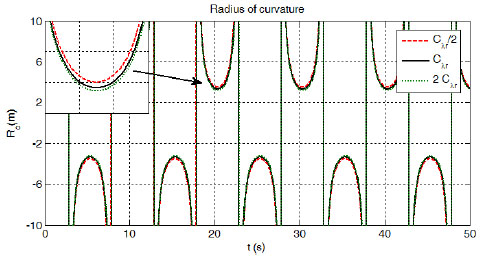 |
Fig. (14) Effect of cornering stiffness on slalom curvature radius. |
Fig. (14 ) shows the radii of curvature for the three simulations. It is interesting to notice that the radius tends to ±∞ in the straight segments of the slalom maneuver and has a limited value when the wheelchair is turning. Like in the case of the steady-turning, an increase in the cornering stiffness causes a decrease in the radius of curvature.
From a technical point of view it is possible to state that the high quality tire (A), which has larger cornering stiffness than the low cost tire (B), requires smaller side slip angles and leads to a more precise trajectory of the wheelchair.
6.2. Effect of Self-aligning Torque
Like in the previous case, three simulations were carried out both for the steady- turning and the slalom maneuvers, the self-aligning torque stiffness ranged from half to twice the measured value. Fig. (15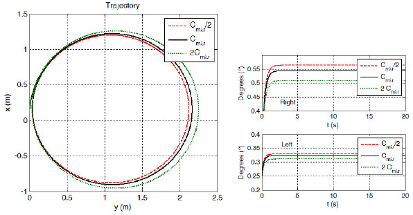 ) shows the effect of self-aligning torque stiffness on the trajectory of the steady-turning maneuver. It is possible to notice that, if the self-aligning torque stiffness increases, the radius of the trajectory increases. The figure also shows that if the value of Cmr increases, the slip angles slightly decrease. These results are consistent because the self-aligning torque causes a decrease in side slip angle and with smaller side slip angles the wheelchair can balance a smaller centrifugal force. Since the forward speed u is constant, the radius of curvature has to increase.
 |
Fig. (15) Effect of self aligning torque on steady turning trajectory of CM and side slip angles. |
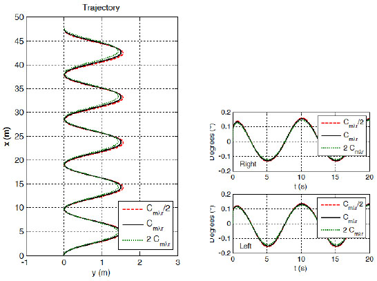 |
Fig. (16) Effect of self aligning torque on slalom trajectory of CM and side slip angles. |
Then the slalom maneuver is considered. Fig. (16 ) shows that, if self-aligning torque stiffness increases, the trajectory tends to become slightly tighter, also in this case it is possible to observe a small lag between the three trajectories. Variations in self-aligning torque show very small effects on the slip angles of the right and left rear wheels.
The trend of the radius of curvature is similar to the one observed in the simulations with varying cornering stiffness, as shown in Fig. (17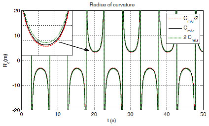 ). The radius tends to ±∞ in the straight segments of the slalom, whereas during the turning phase the radius slightly increases if the self-aligning torque stiffness increases.
 |
Fig. (17) Effect of self aligning torque on slalom curvature radius. |
6.3. Effect of Camber Angle
Some numerical simulations were carried out in order to study the effect of manufacturing errors on wheelchair dynamics. Even if ordinary wheelchair manoeuvres do not involve camber angles of the wheels, a camber angle can occur due to an error in the assembly of one or both wheels. It is worth remembering that equal camber rotations with opposite signs of the two wheels do not generate a net camber force. The camber stiffness and the twisting torque stiffness of the tires were identified during the tests described in the previous section, the values employed in the simulation are shown in Table 1.
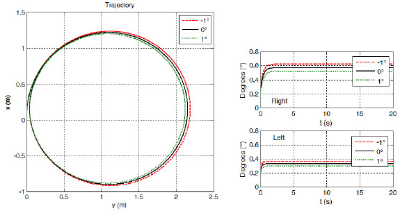 |
Fig. (18) Effect of camber angle on steady turning trajectory of CM and side slip angles. |
A general overview of the graphs that refer to steady turning simulations highlights that moderate values of camber angle have a limited influence on wheelchair dynamics. The effect of camber angle on the trajectory of a steady turning manoeuvre is shown in Fig. (18 ). In the presence of a positive camber angle, the trajectory becomes tighter with respect to the trajectory in normal conditions, whereas with a negative camber angle the trajectory becomes larger. This result agrees with the curves of the slip angles of the right and left wheels. These phenomena take place because in the presence of a positive camber angle the camber force points toward the curve centre and this component adds to side- slip force. Actually the tire behaves as in the presence of an increased cornering stiffness.
The effect of camber angle on the trajectory of a slalom manoeuvre is shown in Fig. (19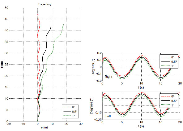 ). For these simulations, only positive camber angles have been analyzed (0°, 0.5° and 1°) because results with negative angles are symmetric with respect to the y-axis. The presence of a positive camber angle generates a positive force which causes the vehicle to drift towards the positive y-axis. This effect can diminish the comfort of the wheelchair during the slalom manoeuvre, since it demands a greater effort from the user in order to keep the vehicle along a straight trajectory.
 |
Fig. (19) Effect of camber angle on slalom trajectory of CM and side slip angles. |
Finally, it is possible to notice that the increase in the camber angle produces a shift in the slip angles of the right and left wheels and the curves become more asymmetric with respect to the x-axis.
CONCLUSION
The experimental tests carried out in the framework of this research show that the characteristic curves of wheelchair tires are similar to the ones of bicycle tires. The dependence on pressure and load of wheelchair tires is similar to the one of bicycle tires. Speed variations in the range 2-4 km/h have negligible effects on tire properties.
For small values of the side slip and camber angles the measured tire forces and torques are well fitted by a linear tire model. If wider ranges of side slip (up to 5°) and camber angles (up to 10°) are considered, more sophisticated tire models are needed to fit experimental results. The Dugoff model appears sufficient to fit tire forces in all the tested conditions, whereas the Magic Formula is needed to fit torques in all the tested conditions.
A linear tire model derived from experimental results has been implemented in a dynamic model of the wheelchair in order to estimate the effect of different tires or different working conditions (load, inflation pressure) on wheelchair handling. Numerical results show that large variations in cornering stiffness and self- aligning torque may lead to variation of 7% in steady turning radius. Cornering stiffness and self-aligning torque produce some effects in the part of a slalom trajectory that shows the smallest curvature radius; it is not clear if the variation of a short part of the trajectory can be perceived by the user.
Finally, the effect of camber angle caused by errors in the assembly of the wheels has been considered. Numerical results show that different camber angles of the two wheels may cause a small drift of the trajectory.
A next step would be the implementation of the wheelchair dynamic model with the tire model in the wheelchair simulator to test the performance and fidelity in the simulated environment with different users. In particular, it should be investigated if and how the variations and effects due to cornering stiffness, self- aligning torque and camber angle affect the fidelity of the wheelchair simulation and the interaction with the wheelchair user.
LIST OF ABBREVIATIONS
CONFLICT OF INTEREST
The authors confirm that this article content has no conflict of interest.
AKNOWLEDGEMENTS
The authors wish to acknowledge Prof. Vittore Cossalter, Head of Motorcycle Dynamics Research Group of Padova University.
REFERENCES
| [1] | R.B. Zoellick, and M. Chan, World Report on Disability. Tech. Report, World Health Organization, World Bank, 2011 |
| [2] | "Guidelines on the provision of Manual Wheelchairs in less resourced settings", In: Disability & Rehabilitation, WHO, 2008. |
| [3] | L.R. Crichlow, "Development of a Comprehensive Mathematical Model and Physical Interface for Manual Wheelchair Simulation", Master’s thesis, University of Toronto, Toronto, Canada, 2011 |
| [4] | S. Advani, M. Potter, and G. Fernie, "CEAL - flight simulation technology applied to rehabilitation research", In: In: AIAA Modeling and Simulation Technologies Conference, Toronto, Ontario, Canada, 2000. |
| [5] | J.J. Chua, F.K. Fuss, and A. Subic, "Non-linear rolling friction of a tyre- caster system, analysis of a rugby wheelchair", Proc. IMechE Part D, vol. 225, pp. 1015-1020, 2010. [http://dx.doi.org/10.1243/09544062JMES2485] |
| [6] | A.M. Kwarciak, M. Yarossi, A. Ramanujam, T.A. Dyson-Hudson, and S.A. Sisto, "Evaluation of wheelchair tire rolling resistance using dynamometer-based coast-down tests", J. Rehabil. Res. Dev., vol. 46, no. 7, pp. 931-938, 2009. [http://dx.doi.org/10.1682/JRRD.2008.10.0137] [PMID: 20104415] |
| [7] | T.G. Frank, and E.W. Abel, "Measurement of the turning, rolling and obstacle resistance of wheelchair castor wheels", J. Biomed. Eng., vol. 11, no. 6, pp. 462-466, 1989. [http://dx.doi.org/10.1016/0141-5425(89)90040-X] [PMID: 2811344] |
| [8] | J. Gordon, J.J. Kauzlarich, and J.G. Thacker, "Tests of two new polyurethane foam wheelchair tires", J. Rehabil. Res. Dev., vol. 26, no. 1, pp. 33-46, 1989. [PMID: 2918486] |
| [9] | D. H. Veeger, and L. H. van der Woude, "The effect of rear wheel camber in manual wheelchair Propulsion", J. Rehab. Res. Develop, vol. 26, no. 2, pp. 37-46, 1989. |
| [10] | V. Cossalter, A. Doria, R. Lot, N. Ruffo, and M. Salvador, "Dynamic properties of motorcycle and scooter tires: measurement and comparison", Veh. Syst. Dyn., vol. 39, no. 5, pp. 329-352, 2003. [http://dx.doi.org/10.1076/vesd.39.5.329.14145] |
| [11] | V. Cossalter, A.E. Doria, A. Doria, L. Taraborrelli, and M. Massaro, "Identification of the characteristics of motorcycle and scooter tyres in the presence of large variations in inflation pressure", Veh. Syst. Dyn., vol. 52, no. 10, pp. 1333-1354, 2014. [http://dx.doi.org/10.1080/00423114.2014.940981] |
| [12] | A. Doria, M. Tognazzo, G. Cusimano, V. Bulsink, A. Cooke, and B. Koopman, "Identification of the mechanical properties of bicycle tyres for modelling of bicycle dynamics", Veh. Syst. Dyn., vol. 51, pp. 405-420, 2012. [http://dx.doi.org/10.1080/00423114.2012.754048] |
| [13] | V. Cossalter, Motorcycle Dynamics, 2nd ed. Raleigh, NC: Lulu.com, 2007. |
| [14] | H. B. Pacejka, Tire and Vehicle Dynamics, Butterworth-Heinemann: Oxford, 2005. |
| [15] | R. Rajamani, Vehicle Dynamics and Control., 2nd ed. Springer US: New York, 2011. |
| [16] | S. Song, M. Chi Kam Chun, J. Huissoon, and S.L. Waslander, "Pneumatic trail based slip angle observer with dugoff tire model", IEEE Intelligent Vehicles Symposium (IV), Dearborn, Michigan, USA, 2014 [http://dx.doi.org/10.1109/IVS.2014.6856538] |
| [17] | B. Johnson, and J. Aylor, "Dynamic modeling of an electric wheelchair", IEEE Transact. Indust. Appl., vol. 2, no. 5, pp. 1284-1293, 1985. [http://dx.doi.org/10.1109/TIA.1985.349556] |
| [18] | T. Gillespie, Fundamentals of Vehicle Dynamics, SAE International: Warrendale PA, 1992. |
| [19] | F. Chénier, P. Bigras, and R. Aissaoui, "A new dynamic model of the manual wheelchair for straight and curvilinear propulsion", In: In:
IEEE International Conference on Rehabilitation Robotics, Rehab Week Zurich, 2011. [http://dx.doi.org/10.1109/ICORR.2011.5975357] |
| [20] | M. Shino, Y. Yamakawa, T. Inoue, and M. Kamata, "Vehicle Longitudinal stability control of electric wheelchairs for persons with severe disability", Veh. Syst. Dyn., vol. 46, pp. 389-402, 2008. [http://dx.doi.org/10.1080/00423110801958584] |