- Home
- About Journals
-
Information for Authors/ReviewersEditorial Policies
Publication Fee
Publication Cycle - Process Flowchart
Online Manuscript Submission and Tracking System
Publishing Ethics and Rectitude
Authorship
Author Benefits
Reviewer Guidelines
Guest Editor Guidelines
Peer Review Workflow
Quick Track Option
Copyediting Services
Bentham Open Membership
Bentham Open Advisory Board
Archiving Policies
Fabricating and Stating False Information
Post Publication Discussions and Corrections
Editorial Management
Advertise With Us
Funding Agencies
Rate List
Kudos
General FAQs
Special Fee Waivers and Discounts
- Contact
- Help
- About Us
- Search


The Open Petroleum Engineering Journal
(Discontinued)
ISSN: 1874-8341 ― Volume 12, 2019
Design and Application of Removable Plugging Slurry for Fractured Carbonate Reservoir
Weian Huang1, 2, *, Zaiming Wang3, Zhengsong Qiu1, Zhongzhi Hu3, Hanyi Zhong1, Yunfeng Liu1, Zhaochuan Li1
Abstract
To meet the requirements of leakage stopping and reservoir protection at the same time in fractured formation, the removable plugging slurries with high temperature tolerance were designed, evaluated and applied in the field successfully. Analysis shows that the fibre materials can deposit onto crack surface, bridge and seal fractures quickly and the selected particles can bridge in throat near wellbore. The comprehensive grading of filling particles was determined from the point of view of gradient filling. The designed plugging slurries KJD155 and KJD200 with higher total dissolution rates sealed 1 mm, 2 mm, 3 mm, and 4 mm crack blocks effectively at room temperature and high temperature (KJD155 at 155 °C; KJD200 at 200 °C) respectively. Their pressure bearing ability of them was up to 5 MPa under bottom hole conditions, which was beneficial to the next operation. Field application of the designed plugging slurries was carried out successfully and showed that they were removable and did smaller damage to reservoir.
Article Information

Identifiers and Pagination:
Year: 2016Volume: 9
First Page: 10
Last Page: 20
Publisher Id: TOPEJ-9-10
DOI: 10.2174/1874834101609010010
Article History:
Received Date: 31/8/2014Revision Received Date: 17/09/2015
Acceptance Date: 20/09/2015
Electronic publication date: 9/3/2016
Collection year: 2016
open-access license: This is an open access article licensed under the terms of the Creative Commons Attribution-Non-Commercial 4.0 International Public License (CC BY-NC 4.0) (https://creativecommons.org/licenses/by-nc/4.0/legalcode), which permits unrestricted, non-commercial use, distribution and reproduction in any medium, provided the work is properly cited.
* Address correspondence to this author at the School of Petroleum Engineering, China University of Petroleum, Qingdao 266580, China; Tel: +86 0532 86981190; Fax: +86 0532 86983030; E-mail: masterhuang1997@163.com
| Open Peer Review Details | |||
|---|---|---|---|
| Manuscript submitted on 31-8-2014 |
Original Manuscript | Design and Application of Removable Plugging Slurry for Fractured Carbonate Reservoir | |
1. INTRODUCTION
Lost circulation is defined as a down-hole troublesome condition in which working liquids (drilling fluid, workover fluid and cement slurry leak into the formation during operation. This has always been a challenge in the petroleum industry [1A. Moazzeni, M. Nabaei, and R. Kharrat, "A breakthrough in controlling lost circulation in a pay zone by optimizing the particle size distribution of shellfish and limestone chips", Petroleum Science and Technology, vol. 30, no. 3, pp. 290-306, 2012.
[http://dx.doi.org/10.1080/10916466.2010.483438] -3A. Ivan, J. Bruton, and B. Bloys, "Lost circulation can be managed better than ever", World Oil, vol. 224, no. 6, pp. 35-39, 2003.]. About 20%-25% of drilled wells have suffered from severe lost circulations. Lost circulation results in as little as the loss of a few barrels of drilling fluid (no effect on drilling) and impaired productivity, as bigger as sidewall instability and drill pipe sticking, or as disastrous as a blowout and loss of life, equipment, or whole assets [1A. Moazzeni, M. Nabaei, and R. Kharrat, "A breakthrough in controlling lost circulation in a pay zone by optimizing the particle size distribution of shellfish and limestone chips", Petroleum Science and Technology, vol. 30, no. 3, pp. 290-306, 2012.
[http://dx.doi.org/10.1080/10916466.2010.483438] , 4V. Murillo, "Lost circulation material", Offshore, vol. 61, no. 7, p. 146, 2001.-6A. Moazzeni, M. Nabaei, and S.G. Jegarluei, "Decision making for reduction of nonproductive time through an integrated lost circulation prediction", Petroleum Science and Technology, vol. 30, no. 20, pp. 2097-2107, 2012.
[http://dx.doi.org/10.1080/10916466.2010.495961] ]. Lost circulation may happen when dynamic bottom hole pressure is greater than formation pore pressure due to pressure surges or improper drilling fluid density. There are four types of formations responsible for lost circulation, natural or induced fractured, vugular or cavernous formations, highly permeable, and unconsolidated formations [7T. Sugama, L. Kukacka, B. Galen, and N. Milestone, "Characteristics of high temperature cementitious lost-circulation control materials for geothermal wells", Journal of Material Science, vol. 22, no. 1, pp. 63-75, 1987.
[http://dx.doi.org/10.1007/BF01160552] -11W.Y. Kai, S.X. Bing, C. Ping, N.R. Guo, L. Qian, L.B. Can, W.X. Ming, and T.G. Quan, "Mechanism study and field application of lost circulation resisting and sealing for formations with low pressure and easy lost circulation", Natural Gas Industry, vol. 24, no. 3, pp. 81-84, 2004.]. Even with the best drilling practices, circulation losses may occur because of their variety of incentives. Lost circulation can be classified into three distinct groups: seepage loss, when the loss rate is 1-10 m3/hr; partial loss, when the loss rate is 10-50 m3/hr; and complete loss, when the loss rate is over 50 m3/hr [1A. Moazzeni, M. Nabaei, and R. Kharrat, "A breakthrough in controlling lost circulation in a pay zone by optimizing the particle size distribution of shellfish and limestone chips", Petroleum Science and Technology, vol. 30, no. 3, pp. 290-306, 2012.
[http://dx.doi.org/10.1080/10916466.2010.483438] , 8W.Y. Zhong, K.Y. Li, Y.L. Jun, and L.J. Jie, "Progresses in mechanism study and control: mud losses to fractured reservoirs", Drilling Fluid & Completion Fluid, vol. 24, no. 4, pp. 74-77, 2007.]. Circulation losses can also be classified into pore throat, fracture, cave and mixed losses according to the shape of leakage channel. The fractures are mostly developed in carbonate rock formation and may be natural or induced during operation. When the downhole pressure exceeds the formation fracture pressure, complete loss will also occur. The aperture, length, distribution density and opening pressure of fractures control the loss rate. Moreover, the fractures in rocks (both natural and induced) have irregular surfaces, the roughness of which has a significant effect on the fracture flow [12L.K. He, "A chemical lost circulation agent for severe leakage in drilling", Open Fuels & Energy Science Journal, vol. 6, no. 1, pp. 48-54, 2013.
[http://dx.doi.org/10.2174/1876973X01306010048] -15N.A. Ghazali, T. Mohd, N.H. Alias, A. Azizi, and A. Harun, "The effect of lemongrass as lost circulation material (LCM) to the filtrate and filter cake formation", Key Engineering Materials, vol. 594-595, pp. 68-72, 2013.
[http://dx.doi.org/10.4028/www.scientific.net/KEM.594-595.68] ]. The fracture surface is usually permeable [5J.L. Chun, C. Mian, H. Bing, S. Zhen, and J. Yan, "Drilling fluid loss model and loss dynamic behavior in fractured formations", Petroleum Exploration and Development, vol. 41, no. 1, pp. 105-112, 2014.
[http://dx.doi.org/10.1016/S1876-3804(14)60012-4] ]. The drilling fluid will leak into formation matrix through fracture surface.
Therefore, the leak-off of the fracture surface will affect the drilling fluid loss dynamics. Leakage control technologies used in stopping fracture losses include static, bridging material, chemical, inorganic gel materials, soft and hard plug sealing [16F. Boukadi, B. Yaghi, H.A. Hadrami, A. Bemani, T. Babadagli, and P.D. Mestre, "A comparative study of lost circulation materials", Energy Sources, vol. 26, no. 11, pp. 1043-1051, 2004.
[http://dx.doi.org/10.1080/00908310490494612] -18J. Kramer, F. Acosta, and P. Thornton, "New technique combats lost circulation", Oil Gas Journal, vol. 101, no. 32, pp. 46-48, 2003.]. Plugging materials and slurries should be different depending on where they are designed to stop the loss of drilling fluid. In the well sections above the cap rock it does not matter what types of material and slurry are used. But in the reservoir interval, in order to prevent productivity damage, sealing materials should be soluble in acid or oil [1A. Moazzeni, M. Nabaei, and R. Kharrat, "A breakthrough in controlling lost circulation in a pay zone by optimizing the particle size distribution of shellfish and limestone chips", Petroleum Science and Technology, vol. 30, no. 3, pp. 290-306, 2012.
[http://dx.doi.org/10.1080/10916466.2010.483438] , 19R. Samavati, N. Abdullah, K.T. Nowtarki, S.A. Hussain, and D.R. Awang, "Rheological and fluid loss properties of water based drilling mud containing HCL-modified FUFU as a fluid loss control agent", International Journal of Chemical Engineering and Applications, vol. 5, no. 6, pp. 446-450, 2014.
[http://dx.doi.org/10.7763/IJCEA.2014.V5.426] ]. Onyia demonstrated the efficiency of calcium carbonate chips, diatomaceous earth, and flake-type materials in oil-based mud, and Hall proposed using perlite for prevention of lost circulation [20E.C. Onyia, "Experimental data analysis of lost-circulation problems during drilling with oil-based mud", Society of Petroleum Engineers, vol. 9, no. 1, pp. 25-31, 1994., 21 Hall, "Bridging effectiveness of perlite for light weight cements and lost circulation", In: AIME 141-G, Fall Meeting of the Petroleum Branch of AIME, Dallas, TX, October 3-5, 1951, Oklahoma City: Oklahoma, 1951, p. 8.].
The fractured carbonate reservoir is developed widely in the buried-hill formation composed of Ordovician and Cambrian system and in beach area of Nanpu Sag, which is the key area for exploration and production in Jidong oilfield [22L.H. Da, X.T. Sheng, and Z.X. Ming, "Reservoir characteristics and well completion technique of jidong buried hill", Special Oil and Gas Reservoirs, vol. 17, no. 2, pp. 116-120, 2010.]. Structural fracture, weathering crack and dissolved fracture are the main reservoir space types of Ordovician buried-hill formation in Nanpu block. Analysis of actual drilling data and final well report of well NP1-80, NP280, NP21-X2460 shows that lost circulations and formation damages have occurred. In this paper, based on investigation into fracture characteristics and lost mechanism, sealing methods and materials were designed, leakage stoppage effect of plugging slurries was evaluated to minimize lost and reservoir damage in oilfield.
2. EXPERIMENTAL
2.1. Materials
Platelike resin, asphalts (softening point: 140-165°C), asphalts (softening point: 190-230°C), fiber JDF(15 mm long) were supplied by the Drilling & Production Research Institute, Petro China Jidong Oilfield Company. Fiber DL-93 (fine) was obtained from SINOPEC Research Institute of Petroleum Engineering, China. Calcium carbonate superfine powder was purchased from Guangzhou Jialiang Minerals Co., Ltd., China. Polymer viscosifier (SDKP) was developed in our laboratory and industrially produced in Chuangxin Science Technology Co., Ltd., Dongying, China.
2.2. Experimental Methods
Dissolution ratio of every lost circulation material was conducted parallel at 80°C for 4 hours. The sealing characteristics of plugging slurries were evaluated using high temperature high pressure circulation simulation device SDY-2 (Fig. 1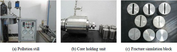 ). The working pressure of SDY-2 is between 0 and 40 MPa, and working temperature is from ambient temperature to 220°C. The shear rate of mixing propeller in pollution still is 0-1000 s-1. The diameter of fracture simulation block is 38 mm, with length of 50 mm. The width of the cracks is from 0.2 mm to 5 mm. Sealing properties of removable plugging slurries were measured using SDY-2 through 1 mm, 2 mm, 3 mm, and 4 mm cracks at room temperature and other setting values.
 |
Fig. (1) Images of parts of the HTHP circulation simulation device SDY-2. |
3. RESULTS AND DISCUSSION
3.1. Fracture Characteristics of Carbonate in Nanpu Sag
It could be observed from Fig. (2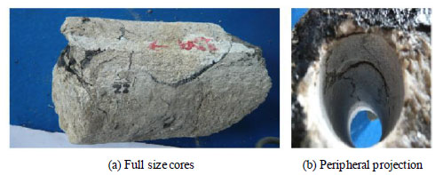 ) that fractures were developed on the cylindrical surface of (a) full size cores and inner cylindrical surface of (b) peripheral projection with different distribution angle. The width of fractures ranged from 0.5 mm to 3 mm. The end face of (a) full size cores was penetrated by fractures. Natural fractures and induced fractures were both found in imaging logging (Fig. 3
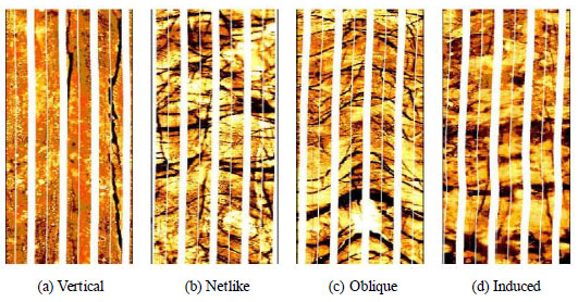 ). Distributional patterns of natural fractures included vertical straight seam, netlike cross stitch, oblique fractures with intersection angles. In well NP280, interval of 4722 m-4732 m develops netlike fractures with strong infiltrability, most branches, high angle, good continuity, with average width of 13 μm, length of 3.93 m/m2, distribution density of 4.89 strips/m, fracture porosity of 0.98% and accompanied by corrosion holes (Fig. 4
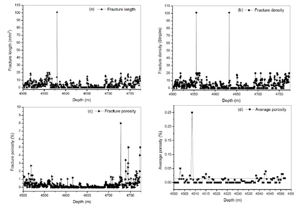 ).
).
 |
Fig. (2) Pictures of fractured carbonate cores from oil-bearing formation. |
 |
Fig. (3) Fracture features in the imaging logging photographs. |
Section of 4542.5 m-4543.5 m has better physical properties and develops most pores. Comprehensive analysis of imaging logging data of Nanpu sag showed that the average fracture width of buried hill carbonate reservoir in 1# structure was 17.5 μm and ranged from 2 μm to 2714.21 μm, fracture width of carbonate in 2# structure ranged from 3.8 μm to 143.56 μm, with average of 40.65 μm, and the average fracture width of carbonate in 5# structure was 3.7 μm (Table 1).
3.2. Leakage Mechanism and Sealing Principle for Fractured Formation
3.2.1. Leakage Mechanism
There are two essential conditions for lost circulation: channels for working liquid flowing through and spaces for containing lost fluids, positive differential pressure between dynamic bottom hole pressure and pore pressure to drive liquid flow from wellbore into formation.
The pressure gradients in carbonate reservoir of Nanpu sag are mostly between 0.98 and 1.04, sometimes more than 1.10. It is easy to build a positive pressure differential between dynamic bottom hole pressure and pore pressure even using non weighted drilling fluid with low content of solids. Moreover, fractures are developed in deep buried hill carbonate reservoir, which provide channels for oil flowing as well as for fluid leakage.

 |
Fig. (4) Fracture parameters from imaging logging interpretations. |
Working liquid losses will occur in natural fractures developed formation when dynamic pressure exceeds fluid pressure in fractures. Lost rate depends on the pressure difference between dynamic pressure and pore pressure, development level, interconnected status, width, length of natural fractures, and rheological properties of liquids in porous media. Lost circulation caused by induced fractures may occur during engineering practice. Reasons for producing induced fractures include the vibration of drill stem joint, stress release of formation and induced fracturing by higher dynamic pressure in wellbore. Generally, fractures induced by vibration of drill string and stress release will not lead to serious fluid losses, while fractures resulting from fracturing or opened by pressure may bring about severe lost circulation. Induced fractured leakage will be generated under the following four conditions: fracturing low pressure formations using drilling fluid with higher density during drilling high (a) Full size cores (b) Peripheral projection (a) Vertical (b) Netlike (c) Oblique (d) Induced pressure oil and gas reservoirs; pressure surge caused by rapid lowering of the drill pipe, casing, bit balling and centralizer mud packing into the hole; the shear stress of fluid in wellbore is too high and pump is opened too quickly and the closed natural fractures are opened by dynamic pressure of liquid in wellbore.
3.2.2. Sealing Principle
Bridging material plugging is more convenient, safe and cheap, compared with other leakage control technologies. Fibrous, granular, powder and deformable materials were selected to plug and strengthen fractures.
3.2.2.1. Morphological Features of Fibrous Material and its Plugging Mechanism
The flocculation formed by tens offiber particles is easier to deposit onto crack surface than spherical particle with the same diameter, with higher stability through multipoint attachment even surface contact with the joint surface. The flocculation with lower strength can fill in fracture of any shape due to its easy deforming under pressure and form effective plugging in the entrance of cracks cooperated with rigid particles.
Stress analysis (Fig. 5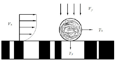 ) shows that the flocculation of fiber particles can settle onto crack surface as:
 |
(1) |
Where, Ty is deposition force, N; Tx is shearing force, N; Ff, ratio of deposition force divided by shearing force.
During drilling in fractured formation, value of Ty is often bigger because of larger filtrate of drilling fluid. To meet this condition smaller return velocity of drilling fluid is suggested to gain less Tx value.
 |
Fig. (5) Schematic diagram of forces acting on the flocculation. |
It can be seen from Fig. (6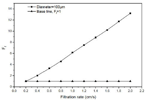 ) that the flocculation fiber particles with diameter of 100 μm can deposit on fracture when filtration rate Vy is more than 0.2 cm/s. As Vy is less than 0.2 cm/s only the flocculation with smaller diameter than 100 μm can settle onto fracture. In practical operation Vy is often greater than 0.2 cm/s. Therefore, fiber agglomerates will bridge and seal fractures in a very short period of time.
 |
Fig. (6) Relation between Ff and filtration rate (diameter of particle is 100 µm). |
3.2.2.2. Bridge Rules of Particles in Fractures
The width of fracture is not well-distributed and can be considered as existence of throat due to tough irregular fractured face. The particle will be stuck in the throat while passing through if its on equivalent sphere diameter is bigger than the width of throat. The bridging distance x obeys exponential distribution. The spread function is as follows:
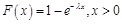 |
(2) |
The probability density function is:
 |
(3) |
Where λ is determined by particle size d and fracture parameter a, σ (σ=D1/2). When λ is bigger, most particles bridge in the position near wellbore, which can be used as bridge particles in plugging. As λ is smaller, the particles bridge in the position far away from wellbore, which enters into the deep part of formation leading to reservoir damage.
Solid particles in plugging slurry have multilevel distribution. The comprehensive grading of three grade filling particles can be calculated from the point of view of step by step filling (Table 2).
3.3. Design of Removable Plugging Slurries
During fluid circulation, near wellbore temperature of buried hill fractured carbonate reservoir is between 50°C-62°C in peripheral projection, 125°C-155°C in 1# structure, 135°C-155°C in 2# structure, 170°C-200°C in 3# structure. The temperature tolerance of plugging materials and slurries should meet temperature in formation where they will be used. Combined with reservoir protection, removable plugging slurry was proposed to stop lost circulation. Plugging method for fluid losses in fractured carbonate reservoir is as follows: bridge firstly with fibrous materials, fill the residual gap with granular, platelike, powder and deformable materials to form impermeable, thin sealed belt quickly. The basic components of plugging slurry include fibrous materials of average sizes, larger particles, thinner platelike materials, fine fiber materials and deformable materials.
Results of resolvability test of lost circulation materials were listed in Table 3. Selected platelike resin and asphalts were soluble in crude oil. Their dissolution ratios were all more than 96%. Calcium carbonate superfine powder, fibers JDF (15 mm long), and DL-93 (fine) were all soluble in hydrochloric acid.
To improve suspension property of plugging materials in slurry, polymer SDKP with high temperature tolerance of 220 °C was selected as viscosifier. The removable plugging slurry formulas aimed at lost circulation in fractured carbonate reservoirs were designed as follows:
The plugging slurry formula used in 1# and 2# structures: 1 % (w/v) SDKP + 1% (w/v) Fiber JDF + 1.5% (w/v) Platelike resin (6mm) + 2% (w/v) Asphalt (softening point: 140-165°C, 3mm) + 1% (w/v) Platelike resin (1mm) + 4% (w/v) Fiber DL-93 + 4% (w/v) Calcium carbonate superfine powder (denoted by KJD155).


The plugging slurry formula used in 3# structure: 1 % (w/v) SDKP + 2% (w/v) Fiber JDF + 2% (w/v) Asphalt (softening point: 190-230 °C, 5mm) + 2% (w/v) Asphalt (softening point: 190-230 °C, 3mm) + 1% (w/v) Asphalt (softening point: 190-230 °C, 1mm) + 4% (w/v) Fiber DL-93 + 4% (w/v) Calcium carbonate superfine powder (denoted by KJD200)
3.4. Evaluation of Removable Plugging Slurries
The total dissolution rates (acid soluble and oil soluble) of the formula KJD155 and KJD200 are 83.18 % and 78.71%. Therefore, sealing belt composed of these lost circulation materials can be removed by acid pickling and dissolving in crude oil.
Results of sealing ability evaluation of removable plugging slurry KJD155 are presented in Table 4. For 1 mm crack block, cumulative leakage of slurry KJD155 was zero at room temperature and 120 °C, 6.8 mL at 150 °C when pressure was up to 5 MPa. For 2 mm crack block, cumulative leakage at room temperature, 120 °C, 150 °C was 1.8 mL, 2.5 mL, 9.9 mL separately. For 3 mm crack block, cumulative leaked volume at room temperature, 120 °C, 150°C was 0.7 mL, 1 mL, 7.3 mL respectively. For 4 mm fracture module, cumulative leakage at room temperature, 120 °C, 150°C was 0.5 mL, 0.8 mL, and 6.3 mL separately. The formula KJD155 sealed 1 mm, 2 mm, 3 mm, and 4 mm crack blocks at room temperature, 120 °C and 150 °C. It could be seen from Table 5 that the formula KJD200 plugged 1 mm, 2 mm, 3 mm, 4 mm crack blocks at room temperature, 180 °C and 200 °C effectively. At room temperature, the cumulative leakage of formula KJD200 through 1 mm, 2 mm, 3 mm, and 4 mm crack blocks was 0, 4.8 mL, 1.6 mL, 5.8 mL separately. At 180 °C, the cumulative leakage of formula KJD200 through 1 mm, 2 mm, 3 mm, and 4 mm crack blocks was 0, 2.8 mL, 2.6 mL, 3.0 mL respectively. At 200 °C, the cumulative leakage of formula KJD200 through 1 mm, 2 mm, 3 mm, and 4 mm crack blocks was 4.4, 9.8 mL, 8.4 mL, and 7.8 mL separately. Before pressuring, cumulative leakage of formulas KJD155 and KJD200 was 0 or small value through different leakage medium, showing that they bridged and filled quickly in fractures to prevent fluid leaking. For the same crack block, cumulative leakages of formulas KJD155 and KJD200 at higher temperature were greater than that at lower temperature, but they were smaller than 10.0 mL (Fig. 7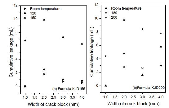 ). Bearing pressure ability of plugging slurries KJD155 and KJD200 was up to 5 MPa, which was beneficial to the next operation such as continuative drilling or completion.
 |
Fig. (7) Relation between Ff and filtration rate (diameter of particle is 100 µm). |
4. FIELD APPLICATION OF REMOVABLE PLUGGING SLURRY
4.1. Field Application in Well NP23-P2006
Well NP23-P2006, a horizontal producing well for developing Ordovician fractured carbonate reservoir, is located at Nanpu sag. Severe lost circulation was encountered during drilling through buried hill at the depth of 5162.98 m. There was no mud return while circulation. The removable plugging slurry KJD200 and cement were adopted after conventional leak stopping was attempted 6 times and failed. Volume of 50 m3 of removable plugging slurries was prepared out of 40 m3 which were pumped into wellbore, followed by 20 m3 cement. The pump pressure did not cut down when stand pipe pressure test was conducted up to 20 MPa, indicating successful sealing operation. Another total loss occured when the well was drilled to the depth of 5179 m. 50 m3 removable plugging slurries were pumped into borehole. The lost circulation was stopped and the circulation of drilling fluid was recovered. The high production capacity was gained during formation testing, showing that the plugging slurries in fractures were removed partly by crude oil and caused small damage to reservoir.
4.2. Field Application in Well G3102-9
Well G3102-9, located at the land area of Bohai Bay, is a directional well for production in Shahejie 3 formation, with design depth of 3937 m. There were no drilling fluids returned when the well was drilled to the depth of 3256 m. Operation of pulling out was performed at once and the drilling fluid was pumped in continuously. However, liquid level in borehole descended once pump was stopped. Loss rate was up to 53.4 m3/h. Volume of 70 m3 removable plugging slurries (KJD155) were pumped into downhole. Lost circulation rate decreased to 18 m3/h after static sealing for 18 hours. Another 70 m3 removable plugging slurries (KJD155) with extra 7 % (w/v) expansible plugging materials were prepared and pumped into wellbore. Drilling fluid circulation was built after static sealing for 13 hours, showing that the fluid loss was prevented successfully.
CONCLUSION
Natural and induced fractures were both developed in buried hill carbonate reservoir of Nanpu sag. Distributional patterns of natural fractures included vertical straight seam, netlike cross stitch, and oblique fractures. The width of fractures ranged from 2 μm to 2714.21 μm, which required the broad-spectrum of plugging slurry.
The fibre agglomerates will deposit onto crack surface, bridge and seal fractures quickly under practical drilling condition. The particles that bridge form in a throat near wellbore should be selected as bridge particles in leak stopping. Solid particles in plugging slurry have multilevel distribution. The comprehensive grading of filling particles can be determined from the point of view of step by step filling.
The removable plugging slurries KJD155 and KJD200 with higher total dissolution rates sealed 1 mm, 2 mm, 3 mm, 4 mm simulated crack blocks effectively at room temperature and high temperature. Their bearing pressure ability improved to 5 MPa, which was beneficial for the next operation.
Field application of the plugging slurries KJD155 and KJD200 were successful and showed that they were removable and did smaller damage to reservoir.
NOMENCLATURE
DL-93: Short/fine fiber lost circulation material
JDF: Long fiber lost circulation material
SDKP: Polymer viscosifier
CONFLICT OF INTEREST
The authors confirm that this article content has no conflict of interest.
ACKNOWLEDGEMENTs
This work was financially supported by National Science Foundation of China (No. 51374233), Shandong Province Science Foundation (No.ZR2013EEM032), the Fundamental Research Funds for the Central Universities (No. 13CX02044A), the Project of China Scholarship Council (201306455021), China Postdoctoral Science Foundation (No. 2014M551986) and the Postdoctoral Innovative Project Foundation of Shandong Province (No.201303060).
REFERENCES
| [1] | A. Moazzeni, M. Nabaei, and R. Kharrat, "A breakthrough in controlling lost circulation in a pay zone by optimizing the particle size distribution of shellfish and limestone chips", Petroleum Science and Technology, vol. 30, no. 3, pp. 290-306, 2012. [http://dx.doi.org/10.1080/10916466.2010.483438] |
| [2] | M.E. Teel, "Fluids improve cementing, reduce lost circulation", World Oil, vol. 215, no. 5, p. 25, 1994. |
| [3] | A. Ivan, J. Bruton, and B. Bloys, "Lost circulation can be managed better than ever", World Oil, vol. 224, no. 6, pp. 35-39, 2003. |
| [4] | V. Murillo, "Lost circulation material", Offshore, vol. 61, no. 7, p. 146, 2001. |
| [5] | J.L. Chun, C. Mian, H. Bing, S. Zhen, and J. Yan, "Drilling fluid loss model and loss dynamic behavior in fractured formations", Petroleum Exploration and Development, vol. 41, no. 1, pp. 105-112, 2014. [http://dx.doi.org/10.1016/S1876-3804(14)60012-4] |
| [6] | A. Moazzeni, M. Nabaei, and S.G. Jegarluei, "Decision making for reduction of nonproductive time through an integrated lost circulation prediction", Petroleum Science and Technology, vol. 30, no. 20, pp. 2097-2107, 2012. [http://dx.doi.org/10.1080/10916466.2010.495961] |
| [7] | T. Sugama, L. Kukacka, B. Galen, and N. Milestone, "Characteristics of high temperature cementitious lost-circulation control materials for geothermal wells", Journal of Material Science, vol. 22, no. 1, pp. 63-75, 1987. [http://dx.doi.org/10.1007/BF01160552] |
| [8] | W.Y. Zhong, K.Y. Li, Y.L. Jun, and L.J. Jie, "Progresses in mechanism study and control: mud losses to fractured reservoirs", Drilling Fluid & Completion Fluid, vol. 24, no. 4, pp. 74-77, 2007. |
| [9] | Z. Li, K. Hui, C. Liang, Yi. W. Han, and H. Zhong, "A new fuzzy ball working fluid for plugging lost circulation paths in depleted reservoirs", Petroleum Science and Technology, vol. 30, no. 24, pp. 2517-2530, 2012. [http://dx.doi.org/10.1080/10916461003792286] |
| [10] | T. Sugama, L. Kukacka, J. Warren, and B. Galen, "Bentonite-based ammonium polyphosphate cementitious lost-circulation control materials", Journal of Material Science, vol. 21, no. 6, pp. 2159-2168, 1986. [http://dx.doi.org/10.1007/BF00547964] |
| [11] | W.Y. Kai, S.X. Bing, C. Ping, N.R. Guo, L. Qian, L.B. Can, W.X. Ming, and T.G. Quan, "Mechanism study and field application of lost circulation resisting and sealing for formations with low pressure and easy lost circulation", Natural Gas Industry, vol. 24, no. 3, pp. 81-84, 2004. |
| [12] | L.K. He, "A chemical lost circulation agent for severe leakage in drilling", Open Fuels & Energy Science Journal, vol. 6, no. 1, pp. 48-54, 2013. [http://dx.doi.org/10.2174/1876973X01306010048] |
| [13] | Z. Li, Z. Hui, Z. Heng, and Z.M. Wei, "A novel lost circulation material: fuzzy ball working fluids", Advanced Materials Research, vol. 562-564, pp. 146-151, 2012. [http://dx.doi.org/10.4028/www.scientific.net/AMR.465.146] |
| [14] | Y. Mou, M.Y. Feng, L. Gao, L.Y. Jie, C. Ying, Z.X. Yang, and L.H. Tao, "Estimation of wellbore and formation temperatures during the drilling process under lost circulation conditions", Mathematical Problems in Engineering, vol. 2013, pp. 1-11, 2013. |
| [15] | N.A. Ghazali, T. Mohd, N.H. Alias, A. Azizi, and A. Harun, "The effect of lemongrass as lost circulation material (LCM) to the filtrate and filter cake formation", Key Engineering Materials, vol. 594-595, pp. 68-72, 2013. [http://dx.doi.org/10.4028/www.scientific.net/KEM.594-595.68] |
| [16] | F. Boukadi, B. Yaghi, H.A. Hadrami, A. Bemani, T. Babadagli, and P.D. Mestre, "A comparative study of lost circulation materials", Energy Sources, vol. 26, no. 11, pp. 1043-1051, 2004. [http://dx.doi.org/10.1080/00908310490494612] |
| [17] | L. Skinner, "Lost circulation", World Oil, vol. 277, no. 8, p. 17, 2006. |
| [18] | J. Kramer, F. Acosta, and P. Thornton, "New technique combats lost circulation", Oil Gas Journal, vol. 101, no. 32, pp. 46-48, 2003. |
| [19] | R. Samavati, N. Abdullah, K.T. Nowtarki, S.A. Hussain, and D.R. Awang, "Rheological and fluid loss properties of water based drilling mud containing HCL-modified FUFU as a fluid loss control agent", International Journal of Chemical Engineering and Applications, vol. 5, no. 6, pp. 446-450, 2014. [http://dx.doi.org/10.7763/IJCEA.2014.V5.426] |
| [20] | E.C. Onyia, "Experimental data analysis of lost-circulation problems during drilling with oil-based mud", Society of Petroleum Engineers, vol. 9, no. 1, pp. 25-31, 1994. |
| [21] | Hall, "Bridging effectiveness of perlite for light weight cements and lost circulation", In: AIME 141-G, Fall Meeting of the Petroleum Branch of AIME, Dallas, TX, October 3-5, 1951, Oklahoma City: Oklahoma, 1951, p. 8. |
| [22] | L.H. Da, X.T. Sheng, and Z.X. Ming, "Reservoir characteristics and well completion technique of jidong buried hill", Special Oil and Gas Reservoirs, vol. 17, no. 2, pp. 116-120, 2010. |