- Home
- About Journals
-
Information for Authors/ReviewersEditorial Policies
Publication Fee
Publication Cycle - Process Flowchart
Online Manuscript Submission and Tracking System
Publishing Ethics and Rectitude
Authorship
Author Benefits
Reviewer Guidelines
Guest Editor Guidelines
Peer Review Workflow
Quick Track Option
Copyediting Services
Bentham Open Membership
Bentham Open Advisory Board
Archiving Policies
Fabricating and Stating False Information
Post Publication Discussions and Corrections
Editorial Management
Advertise With Us
Funding Agencies
Rate List
Kudos
General FAQs
Special Fee Waivers and Discounts
- Contact
- Help
- About Us
- Search


The Open Fuels & Energy Science Journal
(Discontinued)
ISSN: 1876-973X ― Volume 11, 2018
A Regenerative Braking Control Strategy for EVs Based on Real-Time Dynamic Loading of the Wheels
Ning Li1, 2, *, Xiaobin Ning1, Qiucheng Wang1
Abstract
This paper proposes a regenerative braking control strategy based on real-time dynamic loading (RTDL) of wheels. Based on the nonlinear relationship between a spring’s resilience and displacement, this paper establishes 7-degrees of freedom (DOF) full vehicle model with nonlinear suspension. Then, a method based on suspension deformation is devised to calculate the wheels’ dynamic load, and RTDL is used to calculate the braking force of the front and rear wheels. With the braking intensity and the battery state of charge (SOC) as input variables and the desired regenerative braking force as an output variable, we establish a regenerative braking control strategy based on RTDL and simulate it in ADVISOR software. Results show that the designed control strategy effectively improves the regenerative braking energy recovery efficiency by assuring braking stability, and verifies the rationality and feasibility of the proposed control strategy.
Article Information

Identifiers and Pagination:
Year: 2017Volume: 10
First Page: 23
Last Page: 34
Publisher Id: TOEFJ-10-23
DOI: 10.2174/1876973X01710010023
Article History:
Received Date: 09/10/2016Revision Received Date: 17/12/2016
Acceptance Date: 18/12/2016
Electronic publication date: 22/02/2017
Collection year: 2017
open-access license: This is an open access article distributed under the terms of the Creative Commons Attribution 4.0 International Public License (CC-BY 4.0), a copy of which is available at: https://creativecommons.org/licenses/by/4.0/legalcode. This license permits unrestricted use, distribution, and reproduction in any medium, provided the original author and source are credited.
* Address correspondence to this authors at the Zhijiang College of Zhejiang University of Technology, Shaoxing 312030, China; Tel: +86 15957154636; E-mail: wwwningning@126.com
| Open Peer Review Details | |||
|---|---|---|---|
| Manuscript submitted on 09-10-2016 |
Original Manuscript | A Regenerative Braking Control Strategy for EVs Based on Real-Time Dynamic Loading of the Wheels | |
1. INTRODUCTION
Electric vehicle (EV) regenerative braking technology is key to saving energy and protecting the environment. By recovering the consumed energy of the EV in the frictional braking process and releasing it in the driving process, the amount of energy consumed can be decreased and the cruising range can be improved. To recover the vehicle braking energy from the driving wheel to the greatest extent possible along with braking stability whilst preventing wheels from locking, the braking forces of the front and rear axles must be reasonably distributed according to the control strategy [1Shi, Q.S. Key Technologies Research on Energy Management Problems of Pure Electric Vehicles. M.S. thesis, Shandong University: Shandong, 2009.-3Ning, X.B.; Li, N.; Jiang, J.P. Experiment of energy recovery efficiency and simulation research on EV’s regenerative braking system. Comput. Modell. New Technol., 2014, 18(9), 528-533.].
Under the normal braking condition, the braking force distribution strategy is mainly divided into the ideal braking force distribution strategy, the maximum energy recovery strategy and the parallel braking force distribution strategy [4Gao, Y.M.; Chen, L.P.; Ehsani, M. Investigation of the effectiveness of regenerative braking for EV and HEV. SAE Paper 1999-01-2910, , 5Glenn, B.; Washington, G.; Riszoni, G. Operation and control strategies for hybrid electric automobiles. SAE Paper 2000-01-1537,
[http://dx.doi.org/10.4271/2000-01-1537] ]. The ideal braking force distribution strategy generally uses the fuzzy-control algorithm by considering the braking efficiency and SOC synthetically, as well as the distribution of the braking forces on the front and rear axles in the braking process. At present, research mainly focuses on the energy recovery efficiency and the braking distance using a simplified linear vehicle model to study the fuzzy-control rules between input and output variables [6Zhang, G.F.; Zhang, Z.J.; Xie, X.F.; Wang, G.X. Fuzzy logic in regenerative braking of EV. J. Heilongjiang Inst. Sci. Technol., 2012, 22(2), 177-181.-11Gong, X.W.; Zhang, L.J.; Ma, J.; Wang, G.P. Braking force distribution of electric vehicles based on braking stability. J. Chang’an Univ., 2014, 34(1), 103-108. [Natural Science Edition].]. The maximum energy recovery strategy maximises energy recovery through complex control. The present study focuses mainly on meeting braking regulations and achieving vehicle braking stability by studying some complex control strategies and optimisation methods in the simplified linear vehicle model, making the energy recovery efficiency of the vehicle as high as possible [12Guo, J.G.; Wang, J.P.; Cao, B.G. Brake force distribution strategy for electric vehicle based on maximum energy recovery. J. Xi’an Jiaotong Univ., 2008, 42(5), 607-611.-14Yang, Y.J.; Zhao, H.Z.; Mao, F. A study on the control strategy for maximum energy recovery by regenerative braking in electric vehicles. Automot. Eng., 2013, 35(2), 105-111.]. The parallel braking force distribution strategy maintains the original system unchanged, and connected a motor in parallel, by controlling the motor to recover the energy during braking. The present research deals with control strategies for regenerative braking using a linear simplified vehicle model and ensures that the regenerative braking force of the motor and the friction braking force of the original system can be well coordinated and effective at recovering the braking energy [15Wang, X.Y.; Gu, J.C.; Li, Y.H. The simulation for optimisation of parallel regenerative braking control strategy. Comput. Appl. Software, 2010, 27(12), 184-186.-18Wang, M.; Sun, Z.C.; Zhuo, G.R.; Cheng, P. Braking energy recovery system for electric vehicle. J. Transac. Chin. Soc. Agric. Mach., 2012, 43(2), 6-10.]. This research was conducted under ideal conditions using a simplified vehicle model without considering the effects of nonlinear deformation of the suspension on energy recovery when braking, the braking force distribution or the design of control strategy based on the linear formula. In fact, when the vehicle is braking, the suspension produces nonlinear deformation, resulting in the transfer of the front and rear axle loads with the braking deceleration is nonlinear change, and the ideal braking force required by the front and rear wheels with braking deceleration being a nonlinear change, thus causing the early control strategy designed by a simplified vehicle model to become unapplicable.
In this paper, the influence of the suspension’s nonlinear deformation on the energy recovery system is considered in terms of braking energy recovery. We build a vehicle model that considers the suspension’s nonlinear deformation, and a control strategy is proposed for calculating the front and rear wheel’s loads under deformation of the suspension, and in turn, the distribution of the braking force. We establish a regenerative braking control strategy based on RTDL and validate it using simulation with the ADVISOR software, inputting the braking intensity and battery SOC and obtaining the desired regenerative braking force as an output variable.
2. A NONLINEAR GEOMETRIC MODEL OF SUSPENSION FOR A 7-DOF VEHICLE
To study the influence of the front and rear wheels’ braking force on the suspension’s nonlinear deformation, this paper establishes a 7- DOF full vehicle model with nonlinear suspension, as shown in Fig. (1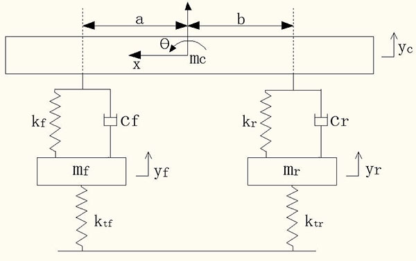 ).
).
 |
Fig. (1) A nonlinear geometric simplified model of the suspension of a 7-DOF vehicle. |
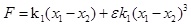
According to refs [19Sheng, Y.; Wu, G.Q. A chaos research on vehicle nonlinear suspension system. Automot. Eng., 2008, 30(1), 57-60., 20Gao, Y.; Fan, J.W.; Pan, S.H.; Li, S.; Kong, F. Fractional-order fuzzy control method for vehicle nonlinear active suspension. Zhongguo Jixie Gongcheng, 2015, 26(10), 1403-1408.], the nonlinear spring-resilience-displacement is expressed as shown in Eqs. (1):
 |
(1) |
where ε is the spring’s nonlinear coefficient.
This paper establishes a suspension force equation while the vehicle is moving according to Eq. (1):
 |
(2) |
 |
(3) |
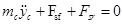
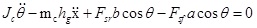
The sprung mass equations of motion are given by
 |
(4) |
 |
(5) |
The unsprung mass equations of motion are
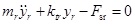 |
(6) |
 |
(7) |
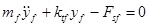
The equations of motion for the wheels are
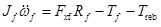 |
(8) |
 |
(9) |
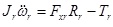
And the wheel force’s equations on the ground are given by
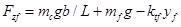 |
(10) |
 |
(11) |
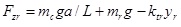
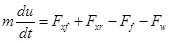
The vehicle’s longitudinal kinetic equations are
 |
(12) |
 |
(13) |
 |
(14) |
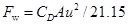
Here, Fsf and Fsr are the forces on the front and rear suspensions, respectively, N; yc is the displacement of the sprung mass, m; a is the distance from the centre of mass to the front axle, m; b is the distance from the centre of mass to the rear axle, m; L is the wheelbase, m; θ is the pitch angle of the vehicle when braking, deg; kf and kr are the spring stiffnesses of the front and rear suspensions, N/m; yf and yr are the unsprung mass displacements of the front and rear suspensions, m; cf and cr are the damping coefficients of the front and rear suspensions, N/m/s; mc is the sprung mass, kg; Jc is the pitching moment of inertia of the sprung mass, kg∙m2; x is the longitudinal displacement, m; hg is the height of the vehicle’s centre of mass, m; mf and mr are the unsprung masses of the front and rear suspensions, respectively, kg; Jf and Jr are the moments of inertia of the front and rear wheels, respectively, kg∙m2; ωf and ωr are the angular velocities of the front and rear wheels, rad/s; Rf and Rr are the rolling radii of the front and rear wheels, rad/s; ktf and ktr are the vertical stiffness of the front and rear tyres, N/m; Fzf and Fzr are the normal applied forces of the front and rear wheels on the ground, respectively, N; m is the overall mass of the vehicle, kg; u is the vehicle speed, m/s; Fxf and Fxr are the braking forces on the front and rear wheels from the ground, N; Fy is the tire rolling resistance force, N; Fw is the air resistance, N; f1 and f2 are the rolling resistance coefficients; CD is the air resistance coefficient; A is the vehicle’s frontal area, m2; Tf and Tr are the braking torques acting on the front and rear wheels of the braking system while braking, N∙m; and Treb is the wheel torque supplied by the motor, N∙m.
3. THE PRINCIPLE OF BRAKING FORCE DISTRIBUTION BASED ON RTDL
3.1. Ideal Braking Force Distribution Principle
According to the ideal braking force distribution principle, on a road of any adhesion coefficient, the conditions that occur when the front and rear wheels lock simultaneously are given as follows: the sum of the braking forces on the front and rear wheels is equal to total adhesive force and they also respectively equal to themselves adhesive force [21Yu, Z.S. Automobile Theory, 5th ed; China Machine Press: Beijing, 2009. ], as shown in Eqs. (15 and 16):
 |
(15) |
 |
(16) |
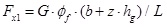
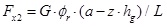
Here, Fx1 and Fx2 are the front and rear wheels’ braking forces, respectively, N; z is the braking intensity; Øf and Ør are the road adhesion coefficients of the front and rear wheels; G is the vehicle weight, N. For the linear vehicle model, as the deformation of the suspension is not considered, the ideal braking force needed by the front and rear wheels can be calculated from formulas 15 and 16.
For the nonlinear vehicle model affected by nonlinear deformation of the suspension, the load transfer between the front and rear axles and the braking deceleration is nonlinear when braking; thus, the front and rear braking forces cannot be distributed according to the linear formula of the ideal braking force distribution principle; in contrast, the front and rear wheel loads are needed to distribute braking force, as shown in Eqs. (17–19):
 |
(17) |
 |
(18) |
 |
(19) |
3.2. Principle of the Braking Force Distribution Based on RTDL
The front and rear wheel loads with brake deceleration variation change constantly under braking because the front and rear suspension stiffness are nonlinear; this makes accurately calculating the front and rear wheels’ RTDL using a linear formula difficult. Therefore, the designed control strategy based on the linear vehicle model cannot guarantee the highest efficiency of energy recovery while also providing the best braking effect.
Therefore, this paper proposes a method to compute the RTDL of the front and rear wheels and to distribute the braking force according to the front and rear loading ratios by measuring the suspension deformation. While the vehicle is moving, the displacement (or deformation) yf and yr of the sprung masses of the front and rear suspensions, respectively, can be measured using a displacement sensor. We can then calculate the loads on the front and rear axles using Eqs. (10 and 11), and use their distribution ratio to distribute the front and rear wheels’ braking forces, locking them simultaneously with the best brake effectiveness.
A vehicle usually has three running conditions-acceleration, constant velocity and braking, and the unsprung mass displacement also exists in three states-upwards motion, equilibrium position and downwards motion. In designing the control strategy, in order to recover regenerative energy only through braking, we use the measured unsprung mass displacements of the front and rear suspensions, yf and yr, respectively, where the unsprung mass equilibrium displacements of the front and rear suspensions are defined as zero when the vehicle is driving at a constant speed. This displacement is defined as negative as it moves downward with compression of the suspension and positive when it moves upward with the suspension’s stretching. When the unsprung mass displacement of the front suspension is negative and that of the rear suspension is positive, we can distribute the braking forces of the front and rear wheels. In other cases, the unsprung mass displacements of the front and rear suspensions will be reset to zero, and no further steps are required. The schematic is shown in Fig. (2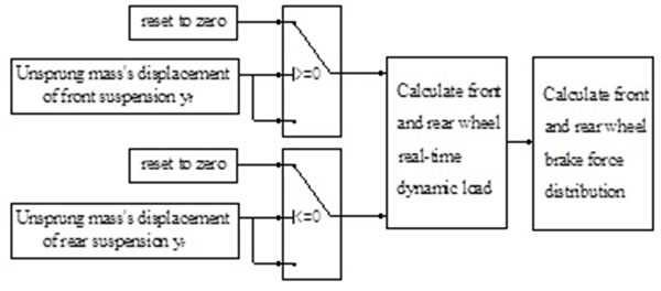 ).
).
 |
Fig. (2) Principle of calculating the braking forces of the front and rear wheels braking through unsprung mass displacement. |
To recover as much energy as possible whilst ensuring the automobile brake stability, we define the total of braking force to be taken on by the drive wheels when the braking intensity is relatively small (z ≤ 0.1), and the rear wheel does not participate in vehicle braking. When the braking intensity is (z > 0.1), the braking force of the front and rear wheels will be distributed by RTDL, and the calculation process of the braking force distribution module based on RTDL is shown in Fig. (3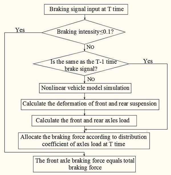 ).
).
 |
Fig. (3) The calculation process of the braking force distribution module based on RTDL. |
4. FUZZY-CONTROL STRATEGY DESIGN FOR THE BRAKING FORCE BASED ON RTDL
4.1. The Principle of the Control Strategy Based on RTDL
With braking intensity z and the battery SOC as the fuzzy controller's input variables and the regenerative brake force coefficient K(regenerative braking force for front axle total braking force ratio) as the output variable, the fuzzy-control tactics schematic will be designed as shown in Fig. (4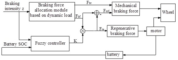 ).
).
 |
Fig. (4) Principle diagram of the fuzzy-control strategy for braking force based on RTDL. |
When braking, the brake signal is transmitted to the brake force distribution module through the driver’s input. This module can distribute the braking forces Fbf and Fbr to the front and rear axles, respectively, according to the input of the braking intensity signal. The braking force required by the rear wheel, Fbr is the mechanical force, while that required by the front wheel, Fbf is the resultant force of the regenerative and mechanical braking forces. At the same time, fuzzy controller calculated the braking force coefficient K according to the input of the braking intensity z and the battery SOC, and with the front axle total braking force Fbf to do product operation; then, we obtain the front wheel’s regeneration braking force Freb. The front wheel’s total braking force Fbf minus the regenerative braking force Freb yields the front wheel’s mechanical braking force Fmf. The mechanical braking forces Fmf and Fbr are the current state of the front and rear wheels that is required to be applied to the friction braking force, Freb is the current state of the front wheel that needs to be applied the regenerative braking force, and accordingly Freb is what needs to be applied to control the motor for braking energy recovery; the recovered energy is stored in the form of electrical energy stored in batteries.
4.2. The Design of the Fuzzy Controller
While braking, the vehicle is significantly affected by road conditions, the driver’s intention and the conditions of the motor and the battery, which will show uncertainty and be nonlinear; it is impossible to express these considerations with a formula. Thus, when we determine the distribution of the braking force, a fuzzy-control technology can be used. Expressing the influence of the different factors (such as braking intensity z and battery SOC) on regenerative braking is easy by means of a fuzzy-logic technique, which can also express control rules that are hard to quantify expediently.
In this paper, a Mamdani-type fuzzy controller is used to control the regenerative and machinery braking forces using the brake intensity z and the battery’s SOC as input variables. The regenerative braking force coefficient K is an output variable. The structure of the controller is shown in Fig. (5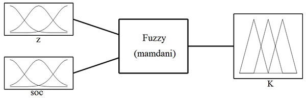 ).
).
 |
Fig. (5) Schematic diagram of the structure of a fuzzy controller. |
The symbol z indicates the input variable braking intensity, which is subjected to a fuzzy transformation to allow it to be described in the fuzzy language. Finally, with fuzzy variables having values of middle-small (MS), small (S), middle (M), big (B) and middle-big (MB), the corresponding fuzzy subsets are set as {MS, S, M, B, MB}, the domain range is [0, 1] and the membership functions are as shown in Fig. (6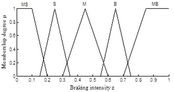 ).
).
 |
Fig. (6) The membership functions of braking intensity. |
The symbol SOC indicates the input variable state of charge of the battery, which is subjected to a fuzzy transformation to allow it to be described in the fuzzy language. Finally, using fuzzy variables having values of very- small(VS), middle-small (MS), small (S), middle (M), big (B), middle-big (MB) and very-big (VB), the corresponding fuzzy subsets are set as {VS, MS, S, M, B, MB,VB}, the domain range is [0, 1] and the membership functions are as shown in Fig. (7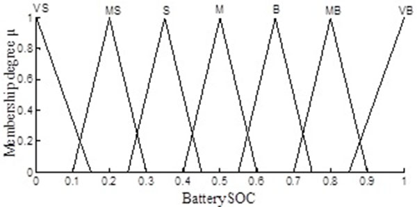 ).
).
The symbol K indicates the output variable regenerative braking force coefficient of front axle total braking force. which is subjected to a fuzzy transformation to allow it to be described in the fuzzy language. Finally, with fuzzy variables having values of very-small (VS), middle-small (MS), small (S), middle (M), big (B), middle-big (MB), very-big (VB), corresponding fuzzy subsets are set as {VS, MS, S, M, B, MB,VB}, the domain range is [0, 1] and the membership functions are as shown in Fig. (8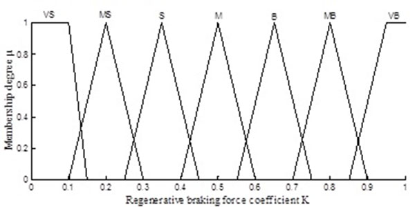 ).
).
 |
Fig. (7) The membership functions of battery SOC. |
 |
Fig. (8) The membership functions of regenerative braking force coefficient K. |
According to the braking intensity z, the battery SOC and the regenerative braking force coefficient K used to design fuzzy controller, the main design principles are as follows:
- When the braking intensity is too high, to brake safely, minimum braking energy should be recovered; when the braking intensity is lower, maximum energy should be recovered.
- When the SOC value is too high, the battery tends to be saturated. Thus, minimum braking energy should be recovered; when the SOC value is lower, maximum energy should be recovered.
Table 1 shows the final design of the fuzzy-rules. Fig. (9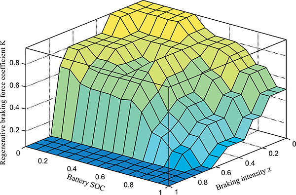 ) shows the corresponding reasoning surface of the fuzzy controller.

 |
Fig. (9) Braking force distribution of the fuzzy controller’s reasoning surface. |
5. CONTRAST ANALYSIS BY SIMULATION WITH ADVISOR
A nonlinear vehicle model and braking force control strategy based on RTDL are constructed with SIMULINK software, and the model is embedded into ADVISOR software for simulation. The vehicle and main system parameters are shown in Table 2. In the simulation model using ADVISOR, the front wheel uses a combination of regenerative and friction braking, whereas the rear wheel uses a pure friction brake. The energy of the front wheel is recovered during braking.
The simulation is completed for two road conditions: the urban dynamometer driving schedule (CYC_UDDS), and the road conditions of the city of Cleveland in the United States of America (CYC_CLEVELAND). The contrast between the two sets of road condition parameters is shown in Table 3. CYC_UDDS are urban road conditions, the speed is low and the braking deceleration is small. CYC_CLEVELAND has high speeds and larger braking decelerations. The designs of the braking force control strategy based on RTDL and ADVISOR's own braking force control strategy are compared and simulated in ADVISOR. ADVISOR's own braking force control strategy was same as the mentioned control strategy of this paper in introduction part; it is based upon a linear vehicle model, and the influence of the suspension deformation upon the regenerative braking is not considered.
Under the CYC_UDDS and CYC_CLEVELAND conditions of the regenerative braking simulation, the battery SOC results under two conditions are shown in Figs. (10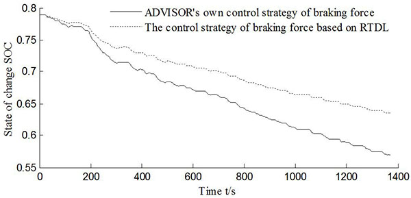 and 11
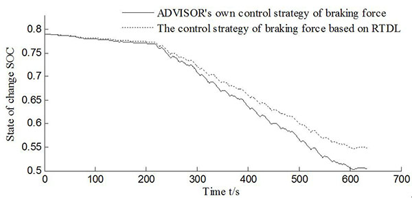 ), respectively. Figs. (12
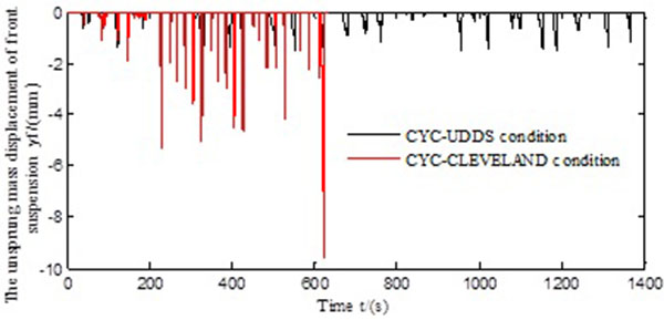 and 13
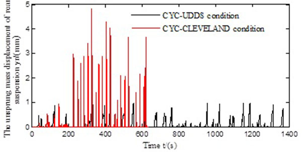 ) are the simulation results of unsprung mass displacement under two conditions; Table 4 compares the results of braking energy recovery under the two control strategies.
 |
Fig. (10) The changing curve of the battery SOC under the circulation conditions of CYC_UDDS. |
 |
Fig. (11) The changing curve of the battery SOC under the circulation conditions of CYC_CLEVELAND. |
As shown in Figs. (10 and 11), the braking force control strategy based on RTDL under both circulation conditions can slow the battery SOC while descending, especially under CYC_UDDS. The residual electricity in the storage battery has larger effects. The battery SOC value is 0.64, which is greater than ADVISOR’s own braking force control strategy's value of 0.57 under the CYC_UDDS circulation condition, and it can also be seen that the battery recovered more braking energy.
The unsprung mass displacements of the front and rear suspensions during braking are shown in Figs. (12 and 13). We can see that those under CYC_CLEVELAND are larger than those under CYC_UDDS, and the braking intensity under the CYC_CLEVELAND circulation condition has a larger intensity. The CYC_CLEVELAND driving time is shorter than that under the CYC_UDDS condition, i.e. 634 s, compared with 1,369 s; thus, the simulation was completed faster for the CYC_CLEVELAND condition.
 |
Fig. (12) The unsprung mass displacement of the front suspension. |
 |
Fig. (13) The unsprung mass displacement of the rear suspension. |
The brake energy regenerations under the different control strategies are shown in Table 4. It can be seen that under the CYC_UDDS condition, the control strategy proposed in this paper is superior to ADVISOR’s own, the regenerative braking energy is increased by 57%, and the braking energy recovery inefficiency is increased by 16.48%. Under the CYC_CLEVELAND condition, the control strategy proposed in this study outperforms that of ADVISOR’s own, the braking energy is increased by 20.67% and the recovery inefficiency of braking energy is increased by 9.6%.
The reason for this difference is the fact that CYC_UDDS represents city road circulation conditions; thus, the vehicle starts and brakes frequently, the average speed is 31.51 km/h and the greatest braking intensity is 0.15 (it is lower than 0.1 during most hours). According to the control strategy proposed in this paper, vehicle braking is often performed by the drive wheels (front wheels), with the rear wheels not participating in braking when the braking intensity is ≤0.1. Thus, the control strategy used in this paper can fully recover the braking energy in the circulation condition of CYC_UDDS. By contrast, ADVISOR's own control strategy for braking force is implemented using the methods of lookup tables, which distribute the front and rear wheels braking force based on the vehicle’s speed, so that under a low braking intensity, there is a lower efficiency of braking energy recovery.
CYC_CLEVELAND offers high speed working conditions; the average speed is 93.14 km/h and the biggest braking intensity is 0.81. Under this circulation condition, the suspension deformation and load transfer are fairly large and represent nonlinear variations along with the brake deceleration. The front axle load calculated by the nonlinear vehicle model is bigger than those of the linear model, so the present front axle braking force is larger. Under the CYC _CLEVELAND conditions, the braking energy recovery efficiency of this paper’s control strategy is higher than that of the ADVISOR’s own control strategy due to the properties of linear and non-linear models.
Because the regenerative braking system and mechanical braking systems work together when the braking intensity is higher than 0.1 under the strategy proposed in this paper, the energy recovery efficiency under CYC _CLEVELAND is lower than that under CYC_UDDS.
CONCLUSION
- According to the nonlinear relationship between a spring’s resilience and its displacement, we established a 7-DOF full vehicle model with nonlinear suspension, considered the nonlinear deformation of suspension's influence upon regenerative braking and proposed a control strategy to distribute the braking force of front and rear wheels based on RTDL.
- With the braking intensity and battery SOC as input variables and the regenerative braking force coefficient as an output variable, we designed a fuzzy controller, and subsequently, a fuzzy-control strategy for braking force based on RTDL is designed. We considered the suspension’s deformation condition, braking intensity and battery power in the distribution of regenerative and machinery braking forces to the front and rear axles.
- Using the ADVISOR software, the control strategy proposed in this paper based on RTDL was simulated and compared with ADVISOR’s own strategy based on a linear vehicle model. The results showed that under the CYC_UDDS condition, the braking energy recovery efficiency of this paper’s control strategy was higher than that of ADVISOR’s own control strategy (16.48%); the same also held under the CYC_CLEVELAND condition, where the braking energy recovery efficiency of this paper’s control strategy was higher than that of ADVISOR’s own control strategy (9.6%).
- Compared with the linear model control strategy used by ADVISOR, the control strategy proposed in this paper is closer to reality and has higher energy recovery efficiency; however, the strategy is complex and difficult to implement.
CONFLICT OF INTEREST
The authors confirm that this article content has no conflict of interest.
ACKNOWLEDGEMENTS
This work is supported by the National Natural Science Foundation of China (No.51375452) and by the fund of Zhijiang College of Zhejiang University of Technology (No.104040120).
REFERENCES
| [1] | Shi, Q.S. Key Technologies Research on Energy Management Problems of Pure Electric Vehicles. M.S. thesis, Shandong University: Shandong, 2009. |
| [2] | Wang, M.; Sun, Z.C.; Zhuo, G.R. Braking energy recovery system for electric vehicle. Trans. Chin. Soc. Agric. Mach., 2012, 43(2), 6-10. |
| [3] | Ning, X.B.; Li, N.; Jiang, J.P. Experiment of energy recovery efficiency and simulation research on EV’s regenerative braking system. Comput. Modell. New Technol., 2014, 18(9), 528-533. |
| [4] | Gao, Y.M.; Chen, L.P.; Ehsani, M. Investigation of the effectiveness of regenerative braking for EV and HEV. SAE Paper 1999-01-2910, |
| [5] | Glenn, B.; Washington, G.; Riszoni, G. Operation and control strategies for hybrid electric automobiles. SAE Paper 2000-01-1537, [http://dx.doi.org/10.4271/2000-01-1537] |
| [6] | Zhang, G.F.; Zhang, Z.J.; Xie, X.F.; Wang, G.X. Fuzzy logic in regenerative braking of EV. J. Heilongjiang Inst. Sci. Technol., 2012, 22(2), 177-181. |
| [7] | Liu, H.; Wang, W.D.; He, J.; Xiang, C.L. Modeling and simulation of the regenerative braking system in a HEV based on fuzzy control. Automot. Eng., 2012, 34(1), 51-56. |
| [8] | Wang, Y.N.; Liu, D.Q. A study of mechanical and electrical compound braking force distribution strategy for electric vehicle. Kongzhi Gongcheng, 2014, 21(3), 348-356. |
| [9] | Zhao, L.; Tang, L.; Wu, X.H. Distribution Strategy for electric vehicle braking force based on fuzzy control. J. Desert Res., 2014, 4(41), 18-21. |
| [10] | Liu, L.J.; Ji, F.Z.; Yang, S.C.; Xu, B. Control strategy for electro-mechanical braking based on curves of ECE regulations and ideal braking force. J. Beijing Univ. Aeronaut. Astronaut., 2013, 39(1), 138-142. |
| [11] | Gong, X.W.; Zhang, L.J.; Ma, J.; Wang, G.P. Braking force distribution of electric vehicles based on braking stability. J. Chang’an Univ., 2014, 34(1), 103-108. [Natural Science Edition]. |
| [12] | Guo, J.G.; Wang, J.P.; Cao, B.G. Brake force distribution strategy for electric vehicle based on maximum energy recovery. J. Xi’an Jiaotong Univ., 2008, 42(5), 607-611. |
| [13] | Zhao, W.Z.; Gu, X.Y.; Wang, C.Y.; Hu, M.Y. Optimisation design of electro-hydraulic brake system with in-wheel electric vehicle. J. Nanjing Univ. Aeronaut. Astronaut., 2013, 45(6), 871-874. |
| [14] | Yang, Y.J.; Zhao, H.Z.; Mao, F. A study on the control strategy for maximum energy recovery by regenerative braking in electric vehicles. Automot. Eng., 2013, 35(2), 105-111. |
| [15] | Wang, X.Y.; Gu, J.C.; Li, Y.H. The simulation for optimisation of parallel regenerative braking control strategy. Comput. Appl. Software, 2010, 27(12), 184-186. |
| [16] | Ko, J.W.; Ko, S.Y.; Kim, I.S. Cooperative control for regenerative braking and friction braking to increase energy recovery without wheel lock. Int. J. Automot. Technol., 2014, 15(2), 253-262. [http://dx.doi.org/10.1007/s12239-014-0026-6] |
| [17] | Zhang, J.M.; Liu, J.L. Parallel composite regenerative braking control strategy for electric buses. Mach. Des. Manuf., 2014, 9(1), 11-18. [http://dx.doi.org/10.1016/j.ijmachtools.2014.02.005] |
| [18] | Wang, M.; Sun, Z.C.; Zhuo, G.R.; Cheng, P. Braking energy recovery system for electric vehicle. J. Transac. Chin. Soc. Agric. Mach., 2012, 43(2), 6-10. |
| [19] | Sheng, Y.; Wu, G.Q. A chaos research on vehicle nonlinear suspension system. Automot. Eng., 2008, 30(1), 57-60. |
| [20] | Gao, Y.; Fan, J.W.; Pan, S.H.; Li, S.; Kong, F. Fractional-order fuzzy control method for vehicle nonlinear active suspension. Zhongguo Jixie Gongcheng, 2015, 26(10), 1403-1408. |
| [21] | Yu, Z.S. Automobile Theory, 5th ed; China Machine Press: Beijing, 2009. |